assembly guide
assembly guide
before you start
Warning
this is a rushed assembly guide... assumes you know how to solder and you already read the bom section and have all of them plus the pcb. while the complexity of the job is low, it may take over 2h of your time to put it together.
Info
familiarise yourself with the pcb
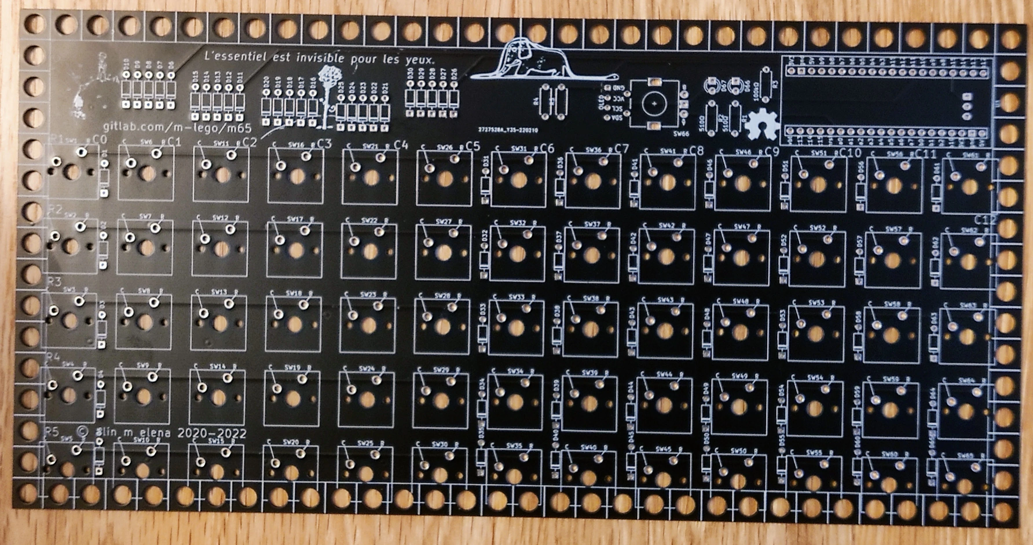
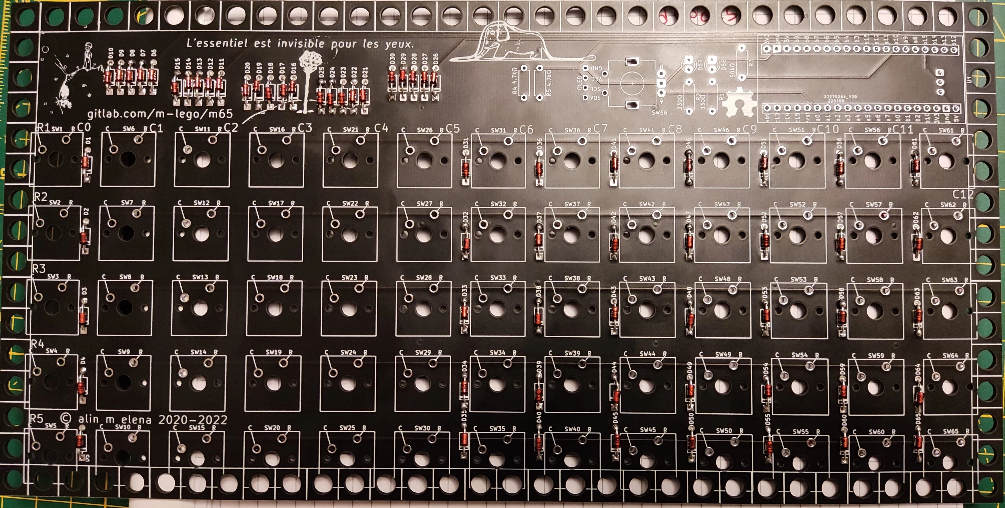
front of the pcb
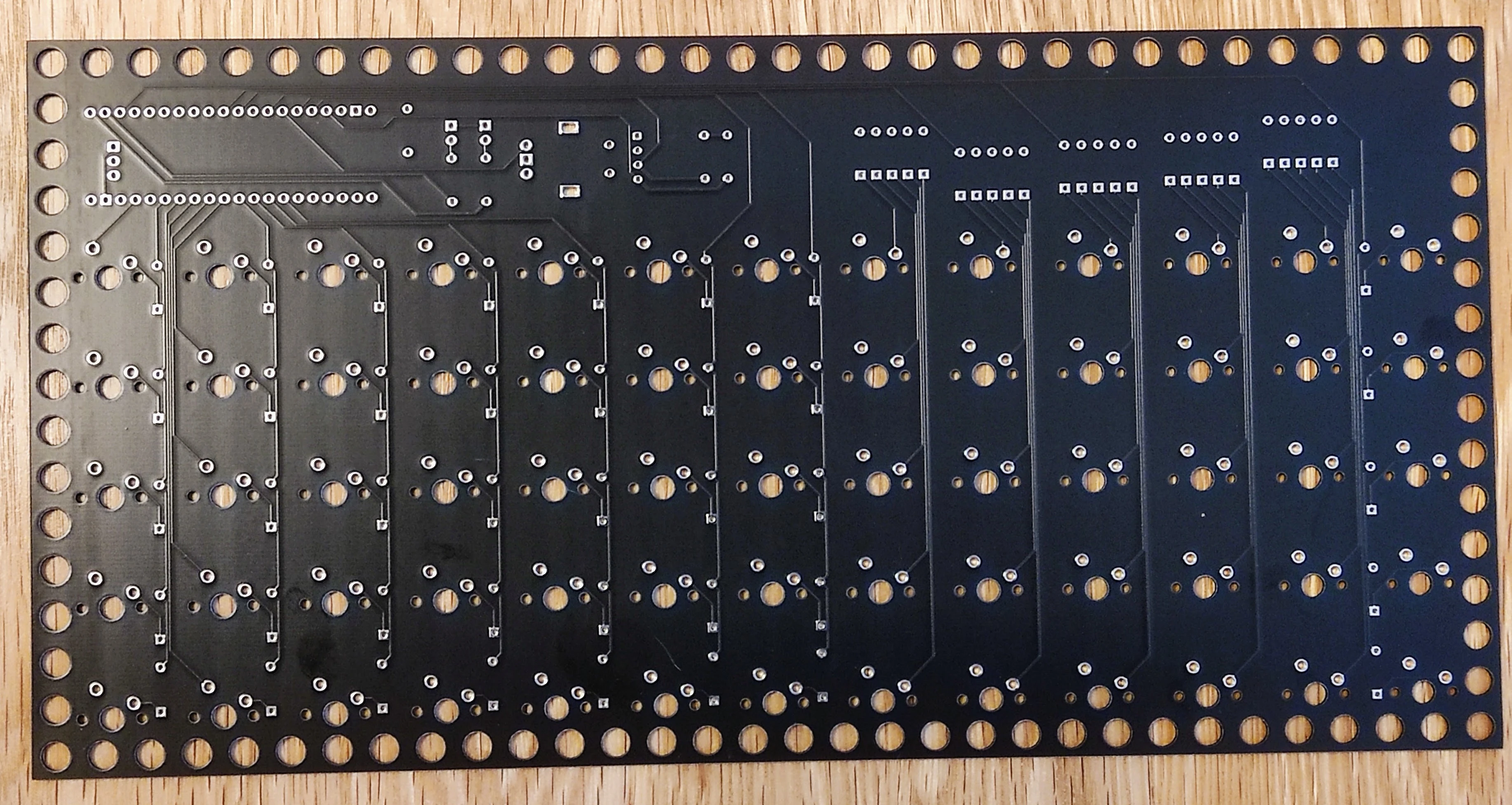
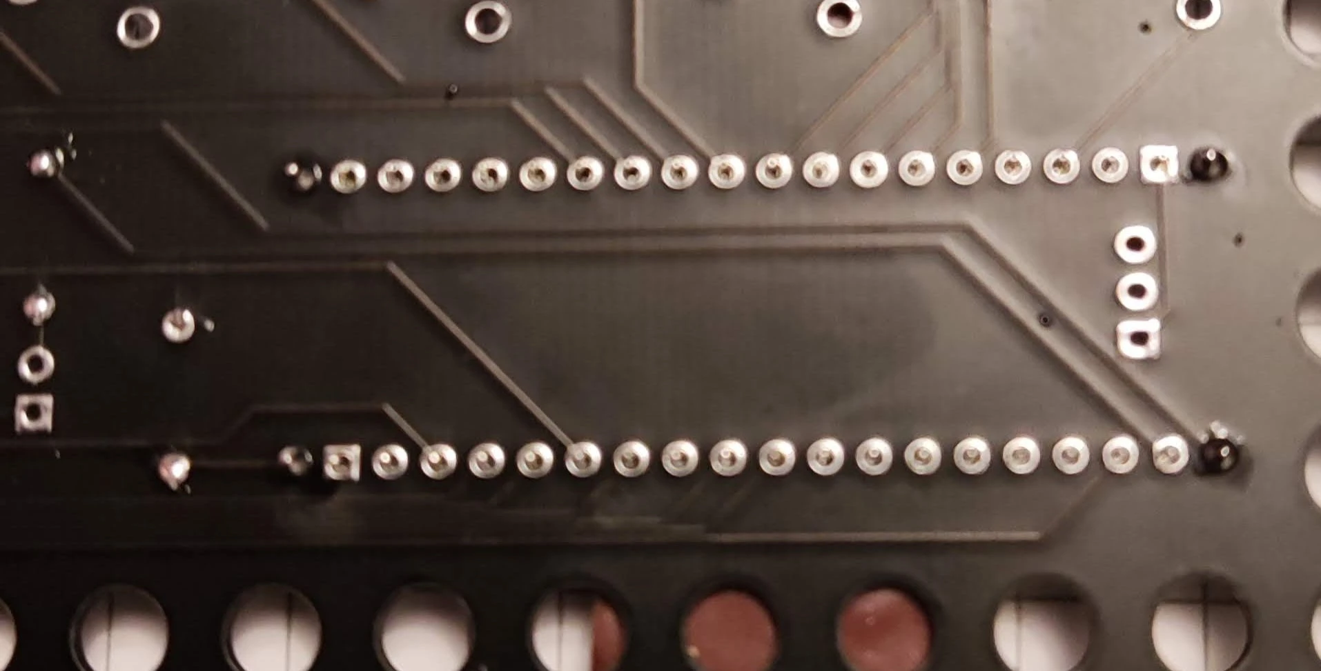
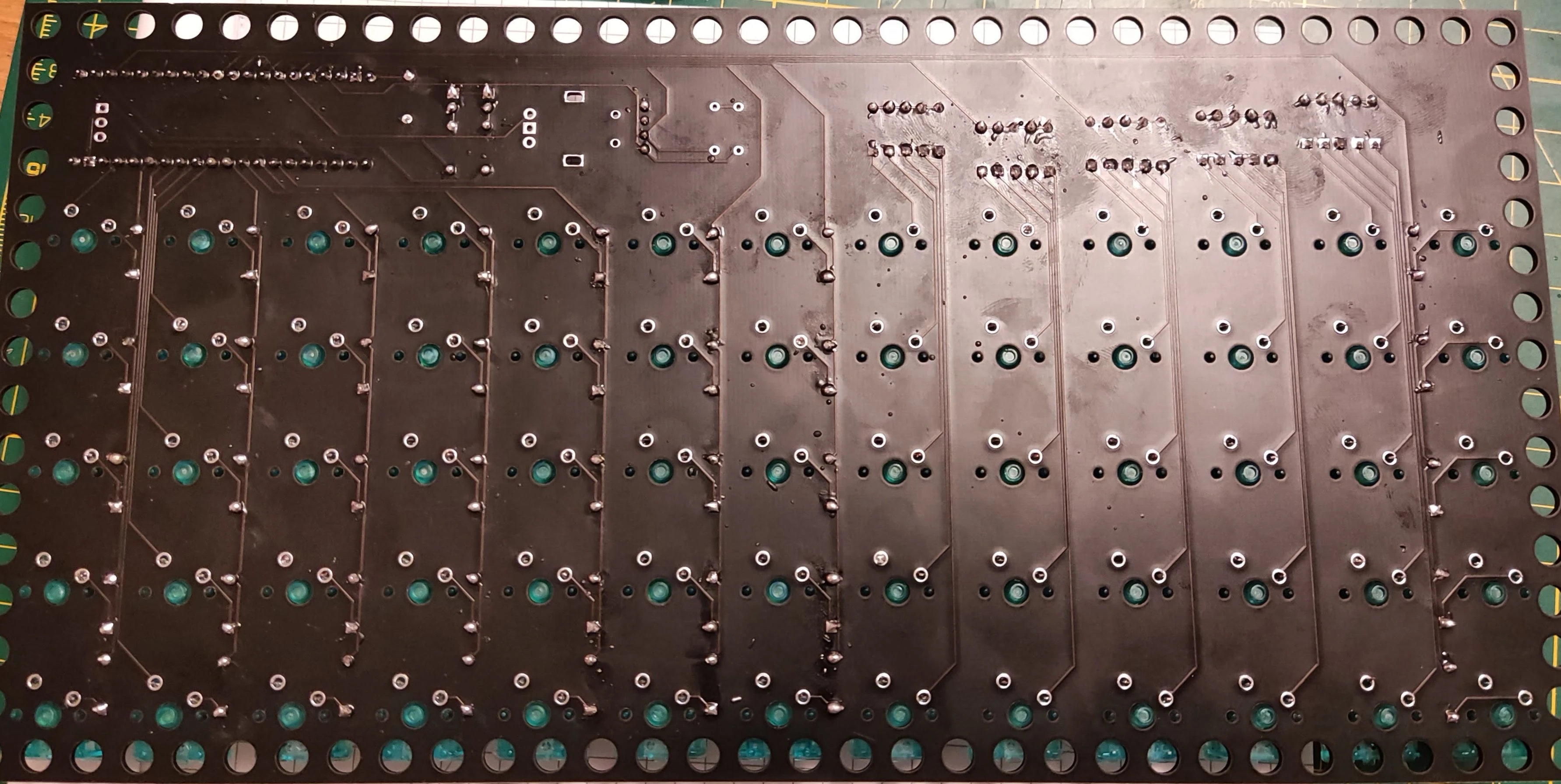
back of the pcb
front of the PCB is the one with the artwork on. you can ignore R4 and R5 since they are for use only in advaced cases when special oleds are used. if you go for the full build all other footprints will be populated.
mcu
Tip
whatever mcu you are using I suggest strongly to socket it.
first step is to add headers on it.
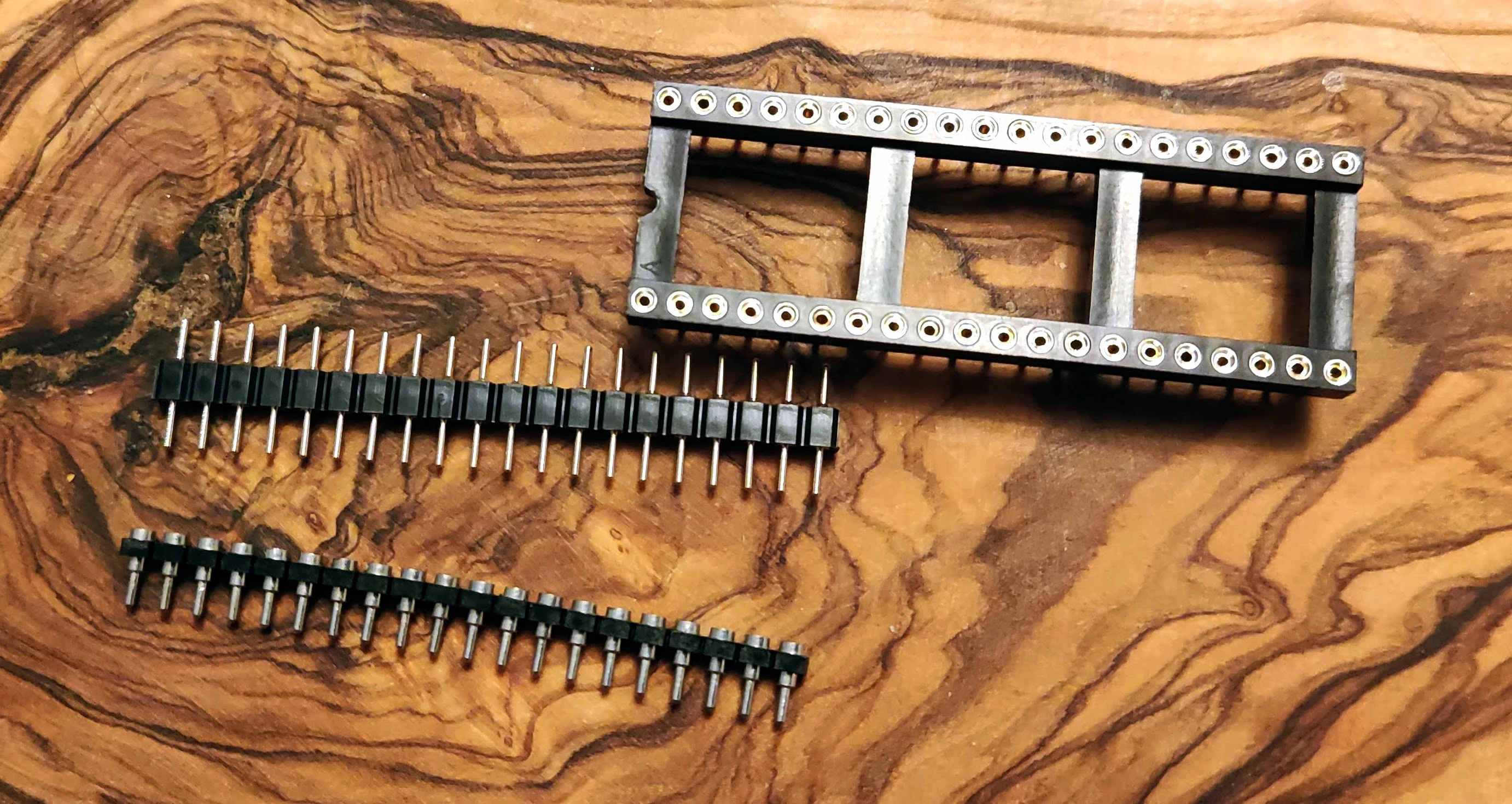
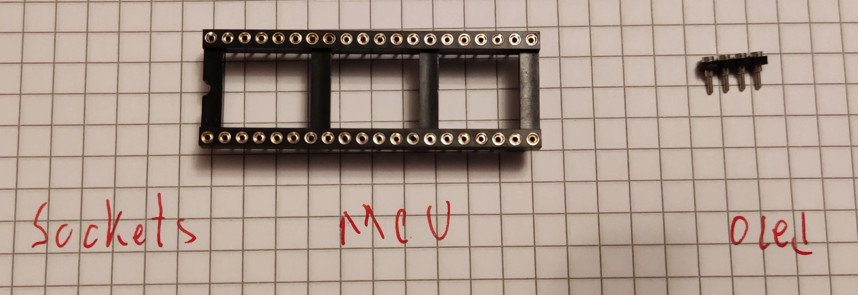
i use round pins and dil sockets, 40 way. picture below
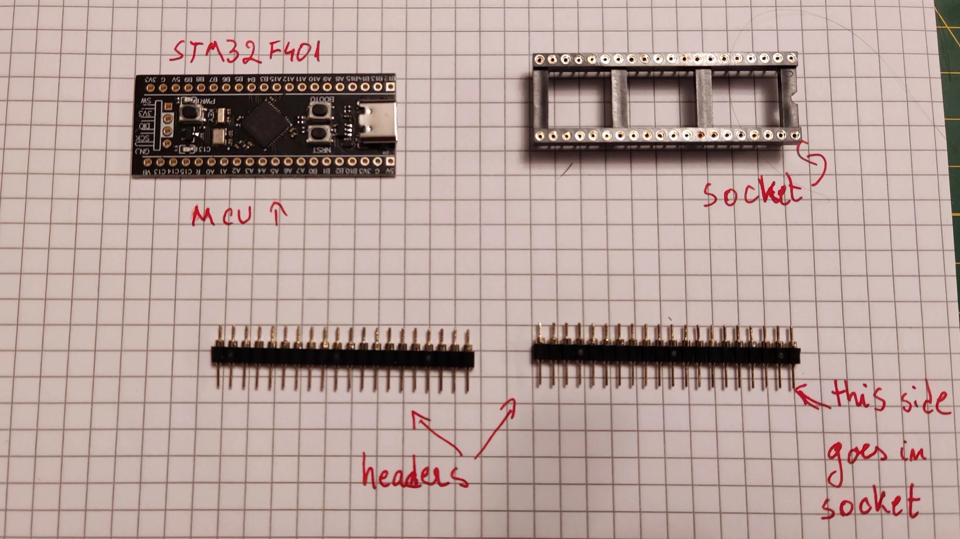
you can also use single row female headers, recommended if you use boards like raspberry pi.
Danger
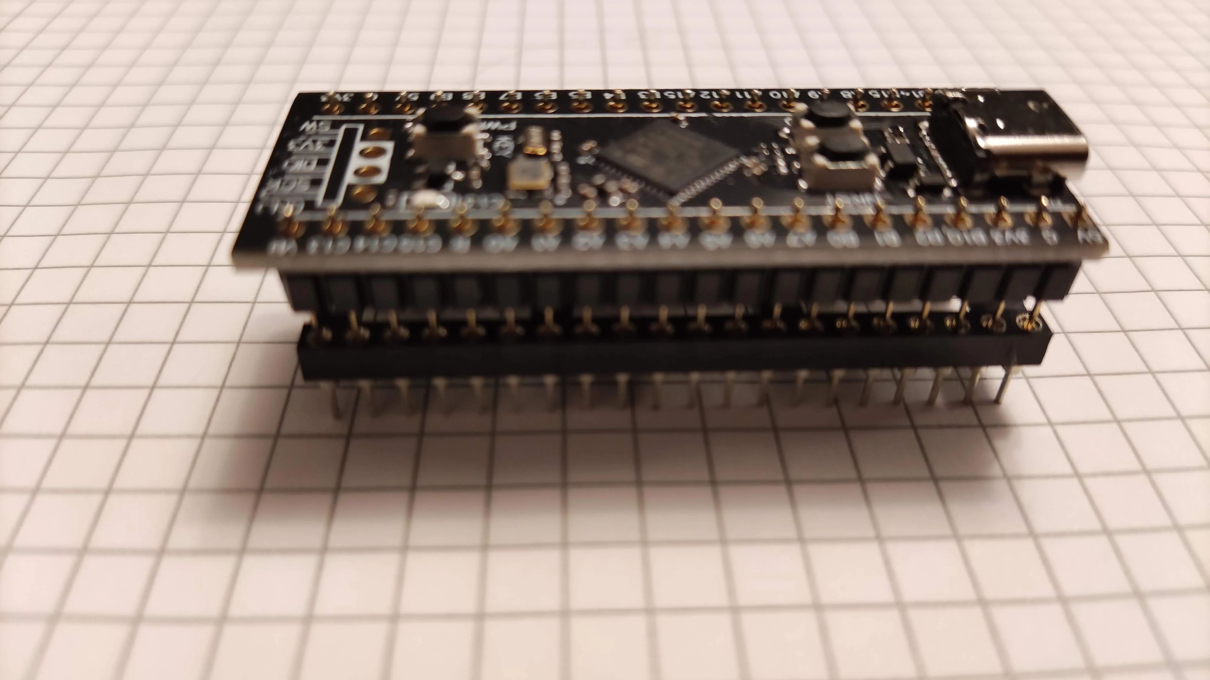
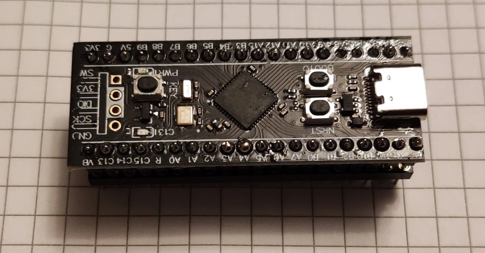
put the headers into the socket no need to fully insert them just be sure the conical bit points towars the socket and the mcu on top. see picture below.
Info
be sure headers are vertical and stable. now you can start soldering.
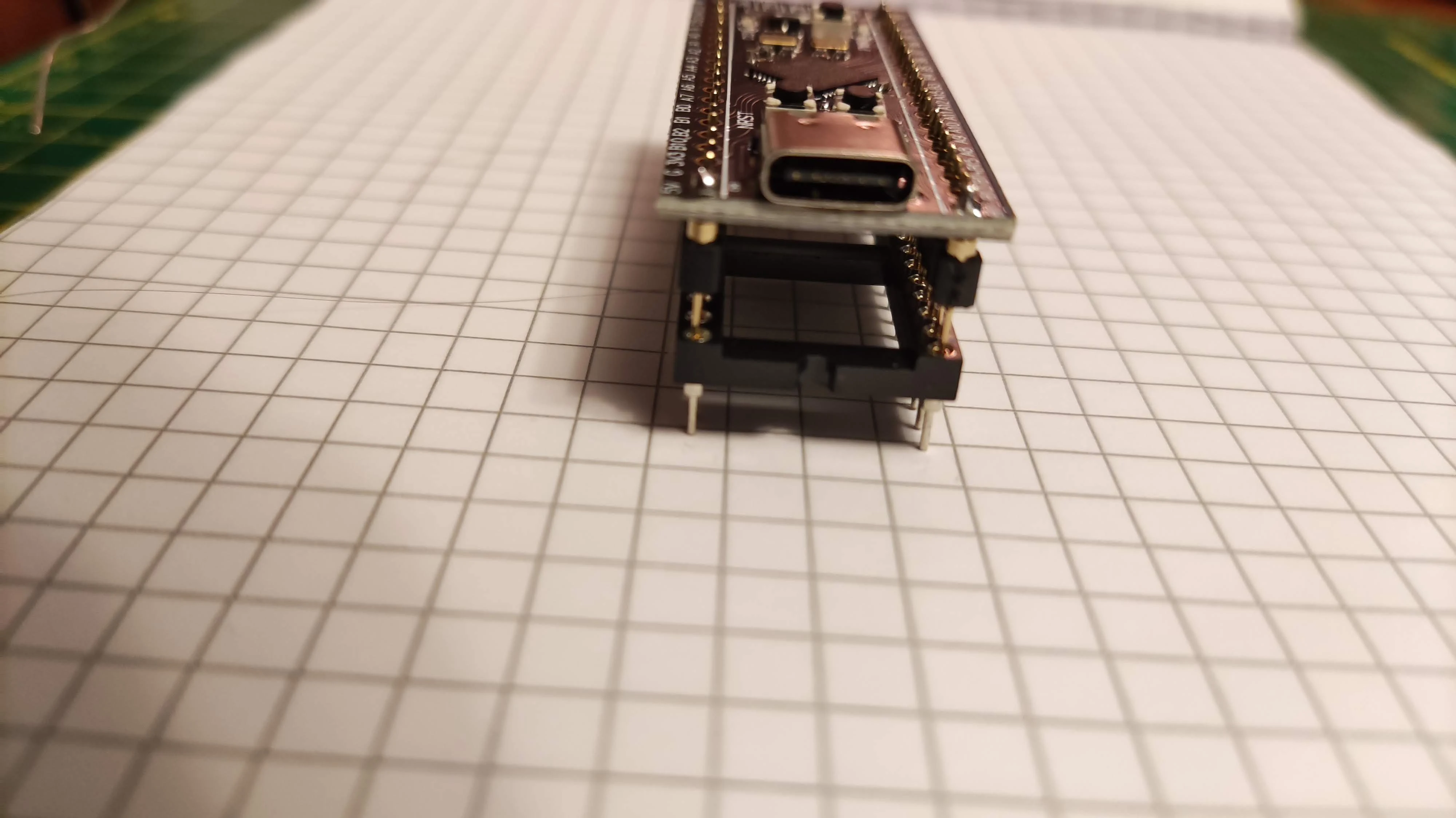
I solder usually the extremes for each row and then the rest.
finally shall look like this

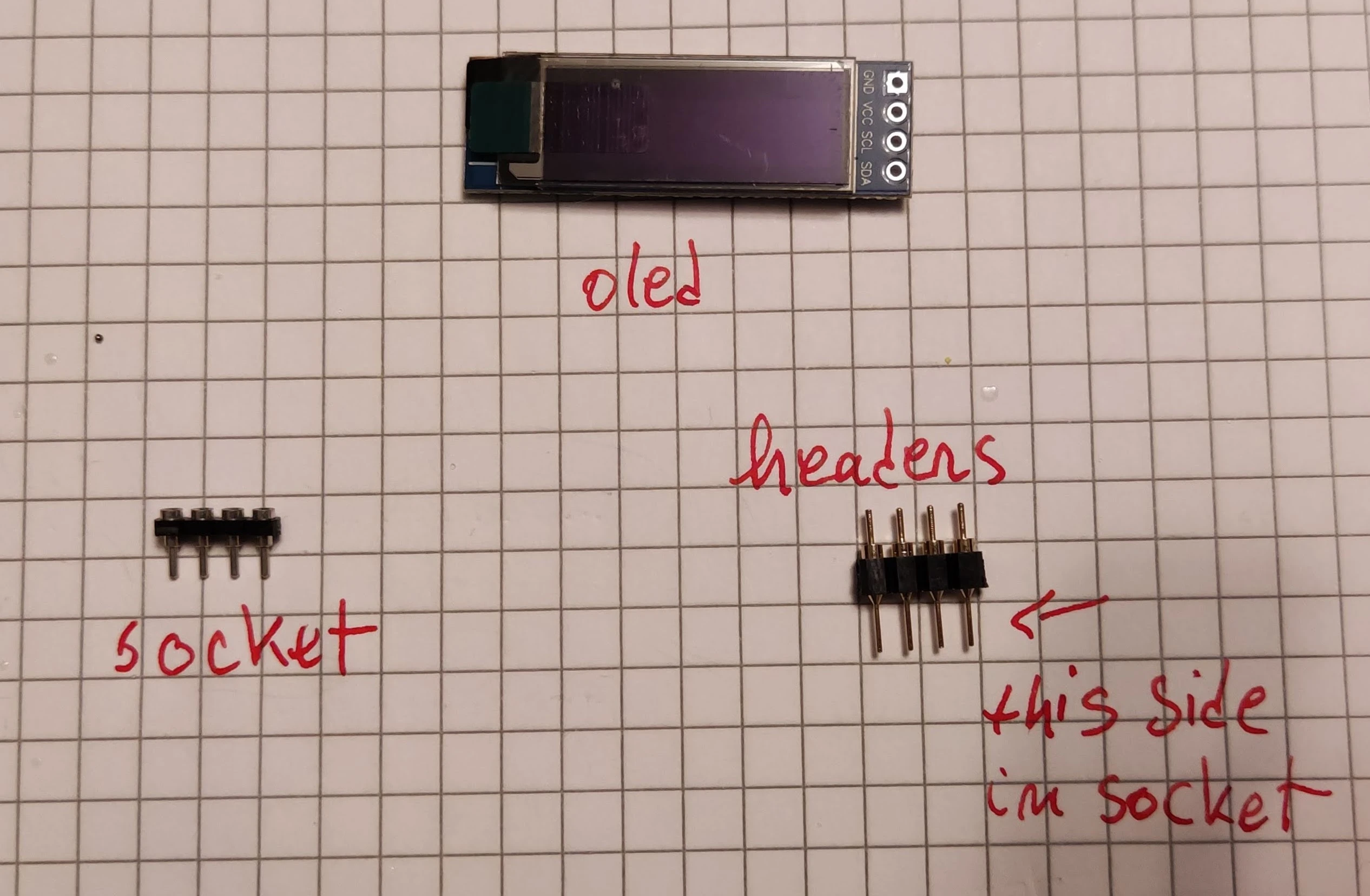
oled
if you are using an oled i suggest to socket it too. Again I use round pins 4 in a row are enough and use a low profile socket, see below.
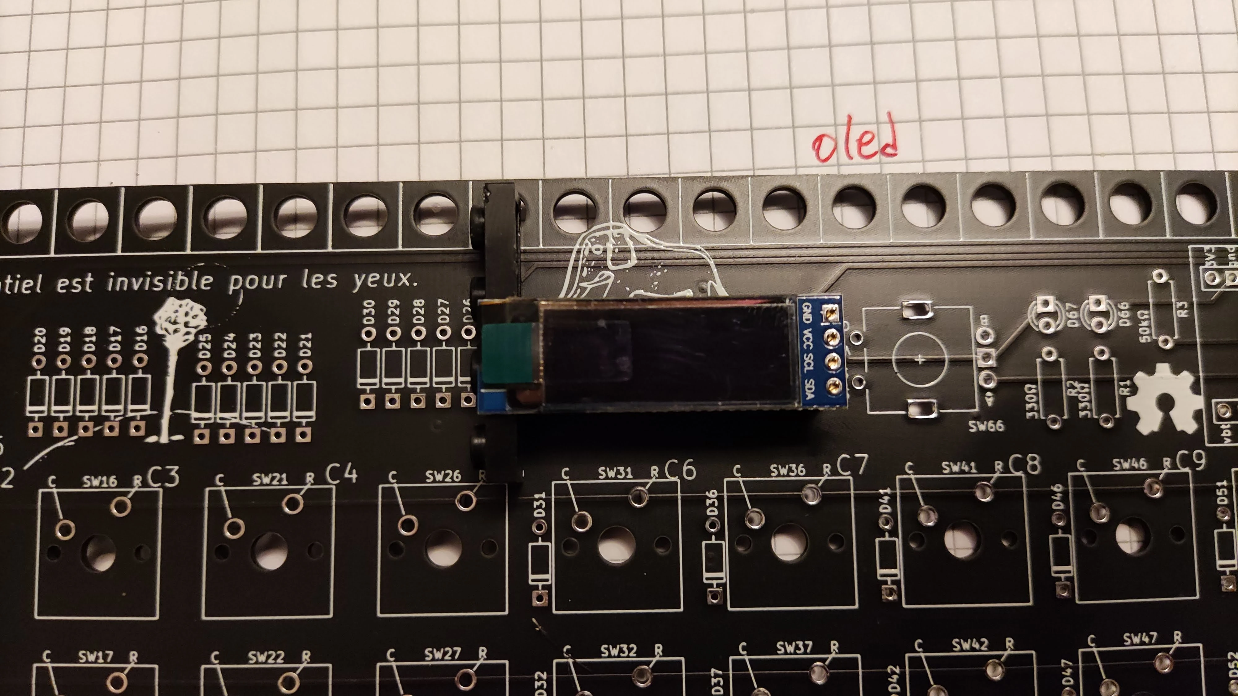
for soldering this you can use the pcb as support. add the headers into the pcb(conical side towards pcb) put the oled on top and be sure is vertical. you can use some blue tack or tape(electrical, painters, etc).
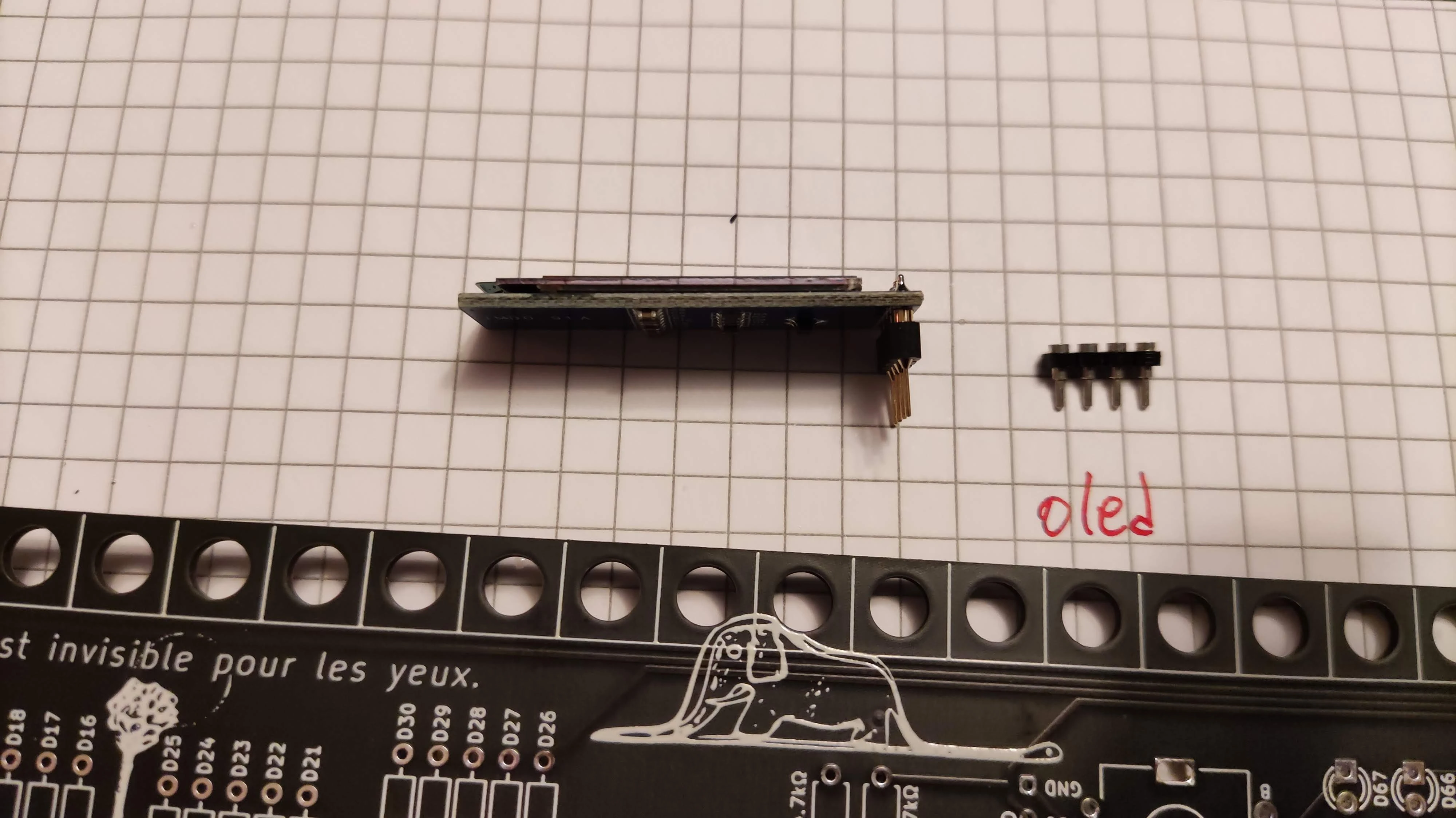
now you can solder the oled(be sure you do not solder the keyboard pcb side). Once done you can remove it from pcb shall look like this.
diodes
get 65 of them 1n4148 do-35, they look like this.

Danger
note the black ring/colar at one end.
bend the legs at 90˚ like in the picture above.
Danger
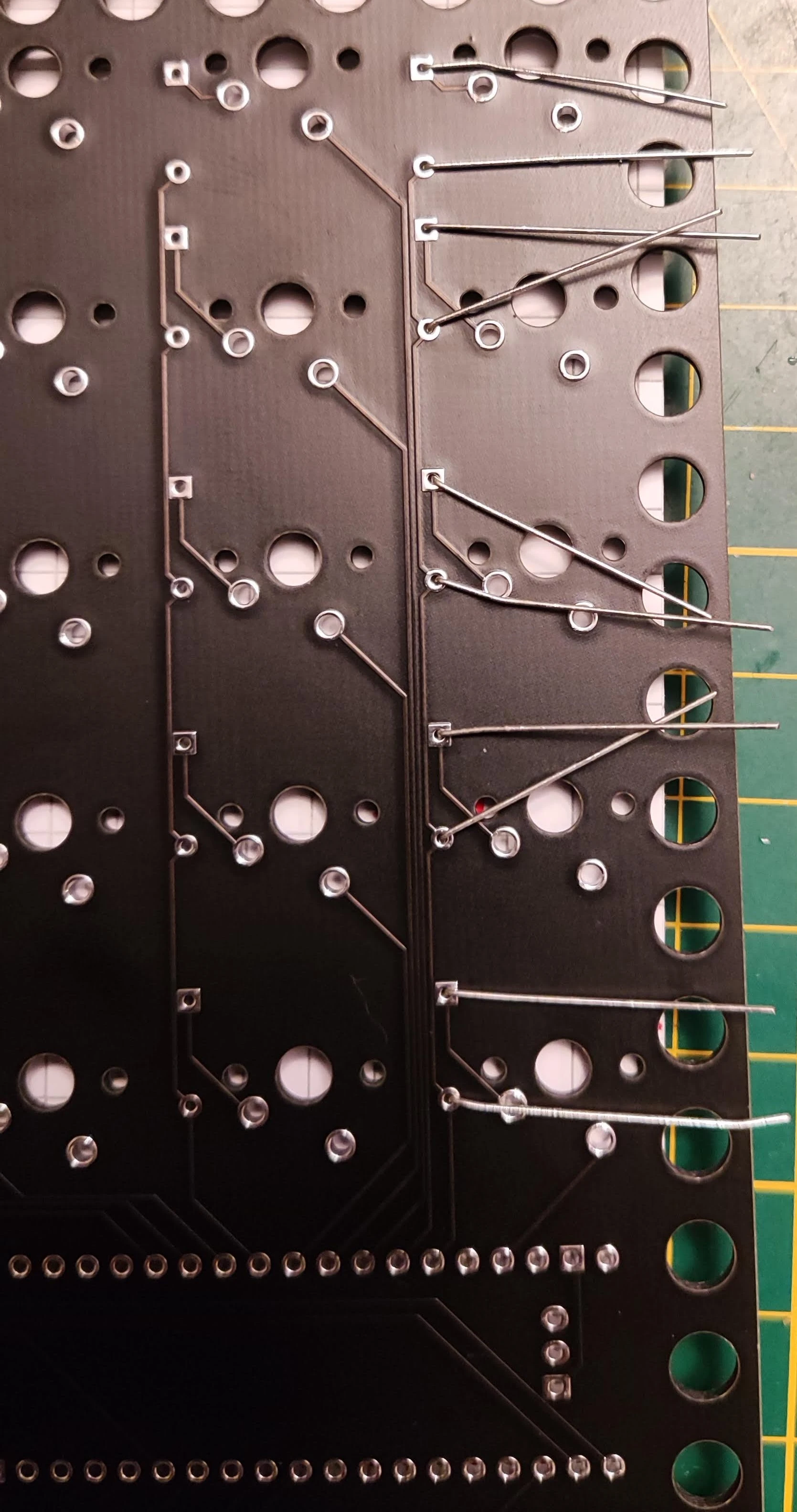
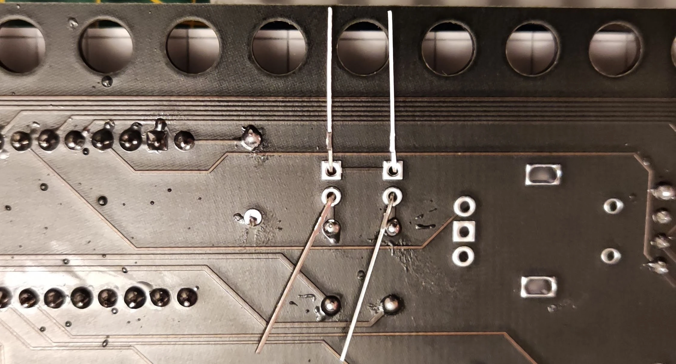
insert them in the holes, with the black colar oriented to the lower part of the board. see picture.
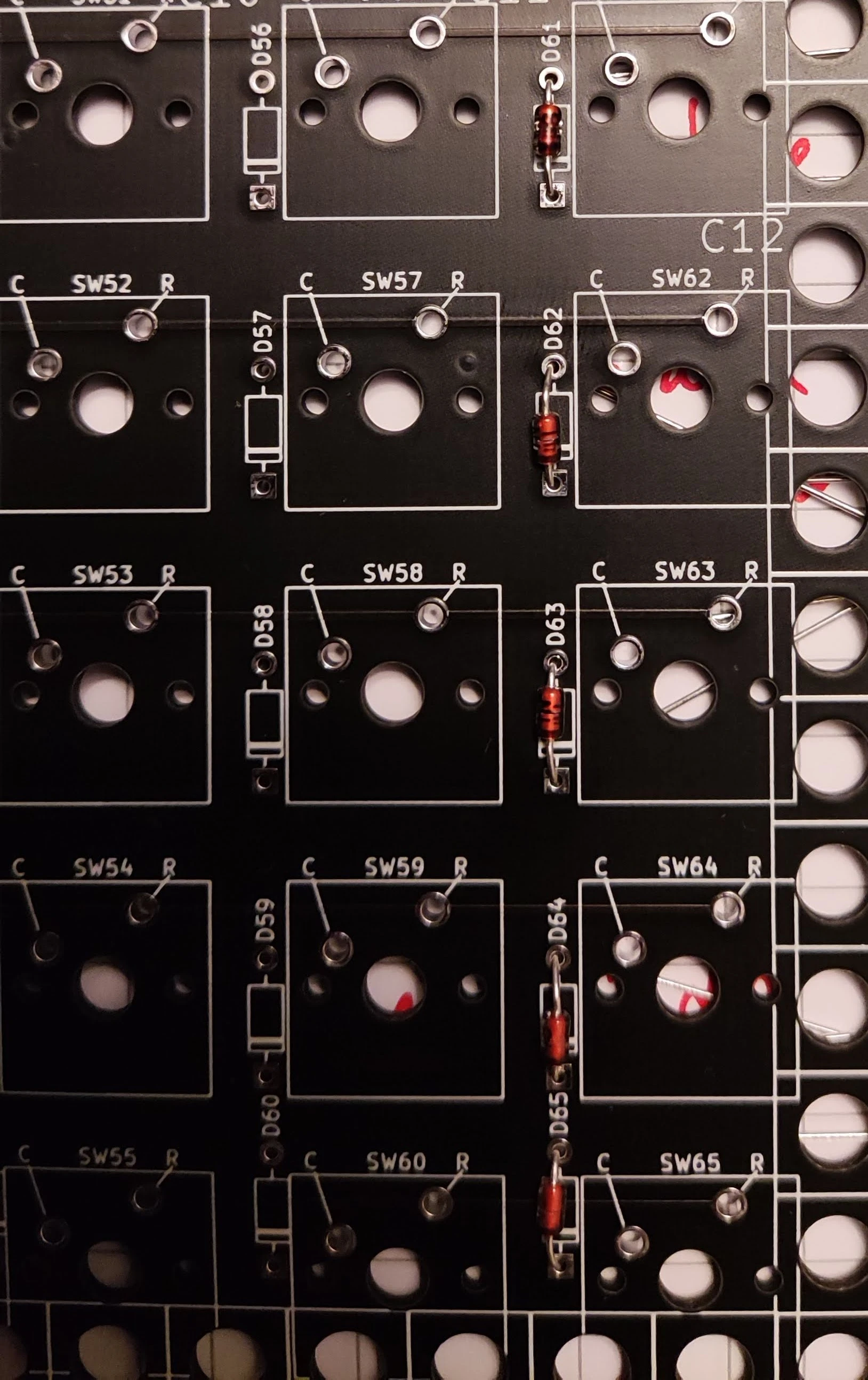
bend the legs on the reverse of the pcb to assure the diode is fixed in the position. bending in the opposite direction helps for better stability during soldering. see picture.
Danger
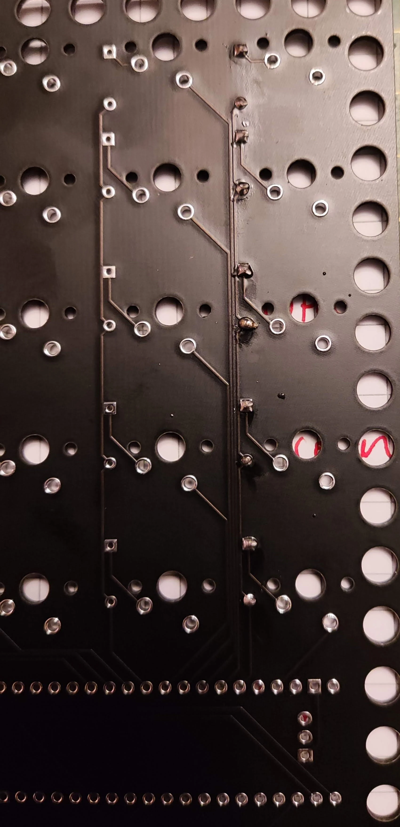
now you can solder, once done, wriggle the legs of the diode until they detach, leaving a clean cut at solder level. you may want to reflow the joint after you remove the leg. wiggling may cause damage to the joint. alternatively use a flush cutter if you have one makes things faster.
see picture
repeat for all the diodes next to the switches. you may find it easier if you work your way for each column.
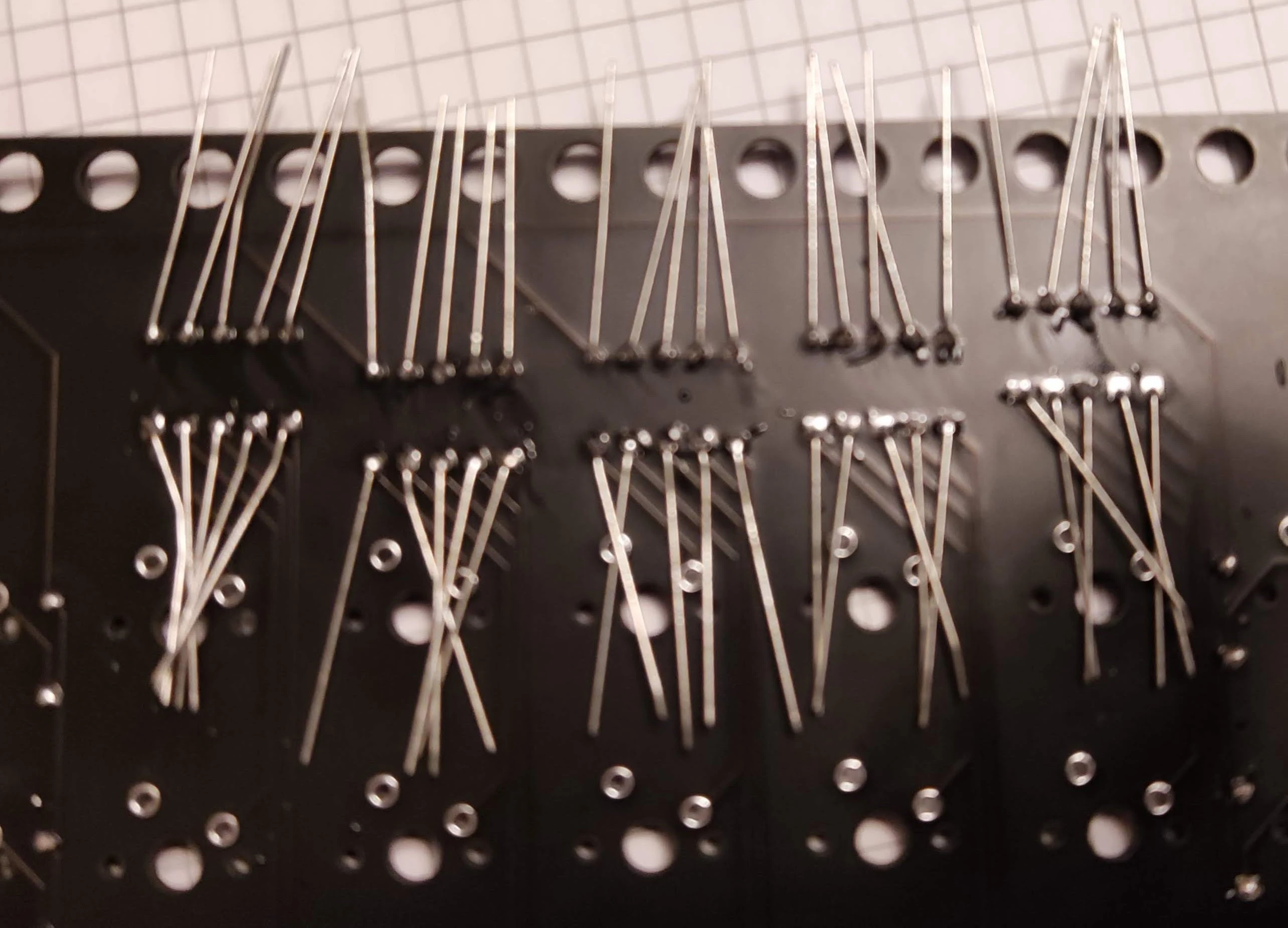
for the diodes at the top, bending shall be done differently, see picture. this allows to add them all in one go.
finally once you are over shall look like this or better
resistors
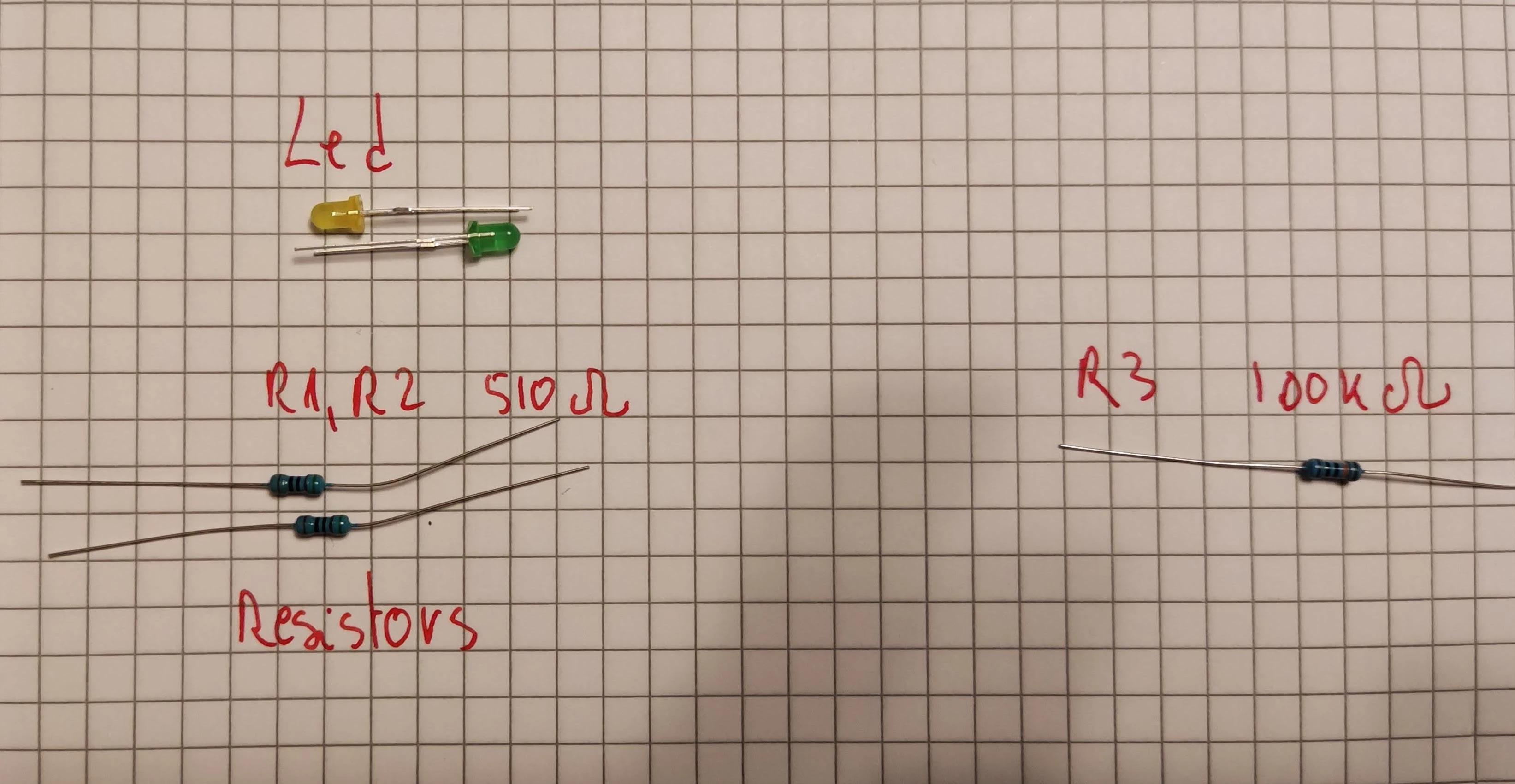
there are max three resistors you need to put procedure is the same as for the diodes, bend, insert, bend. it does not matter how you insert them, just be sure you have the right values in the right places.
Warning
R3 is 100kΩ(you can use 22kΩ). this is needed for blackpill to enter reliably in boot mode
Warning
R1 and R2 need to be calculated based on the colour of the led used and desired intensity. for yellow and green leds I use 510Ω(not very bright) and for white leds 1kΩ (quite bright)
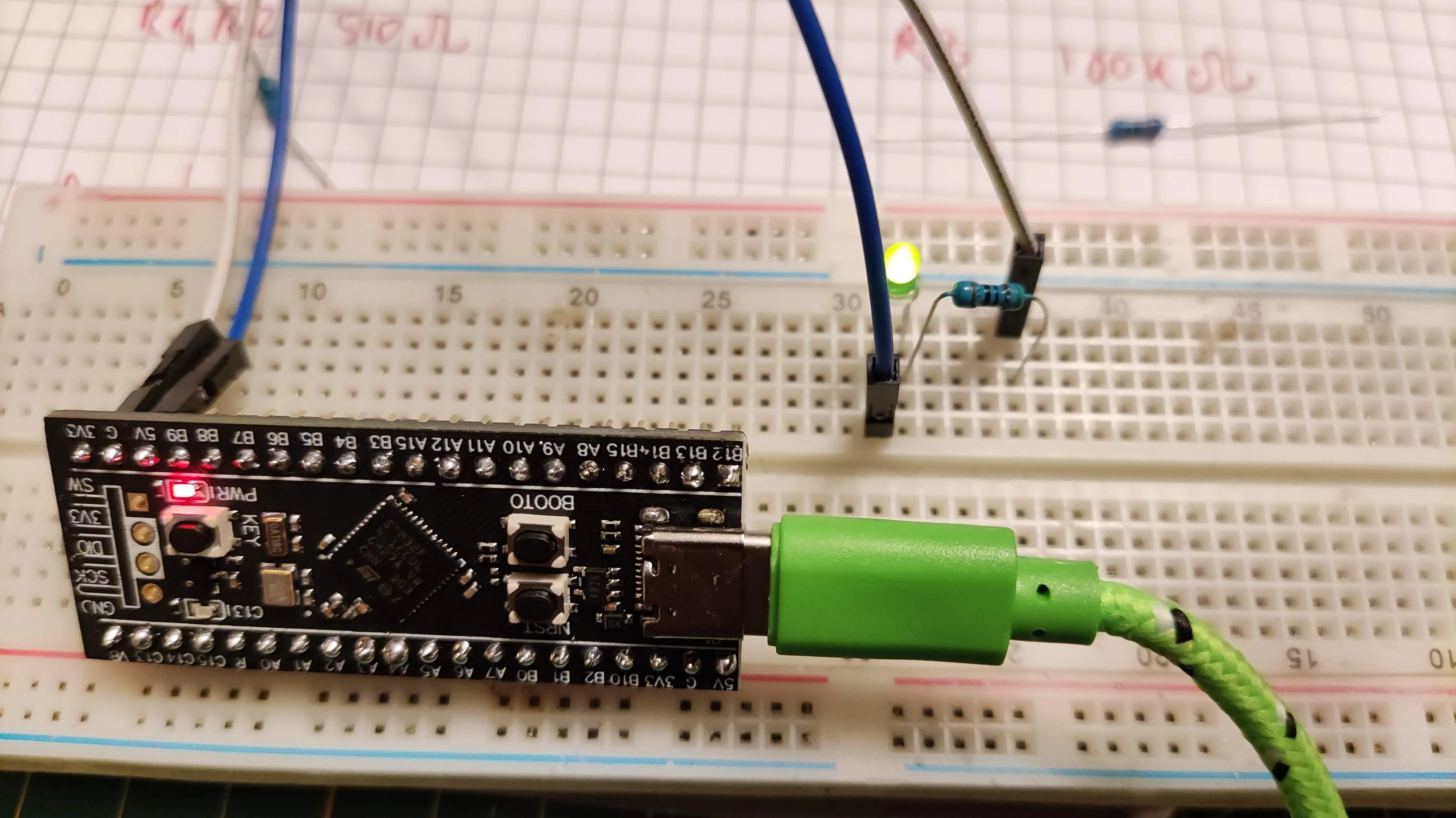
Note
you may want to use a breadboard to test before to see if you are happy with the intensities, use a 3.3V DC source. alternatively you can use the mcu itself. if you do not have a breadboard dupont wires may be enough. also in this step you will determine the led orientation... note which leg goes to 3.3V and which one goes to ground. this step is important since I noticed some of the leds do not follow the convention... long leg positive, short leg negative.
sockets
put the 40 way dil socket into the pcb (front side). secure it with tape.

turn the pcb. you can solder the extreme pins on rows. be sure the socket is properly aligned with the pcb
next repeat the same but with the oled socket.
leds

Danger
put the leds in the right position, matching the resistor value determined before. also you need to be sure the leg that pointed to ground goes in the hole with the square plating. once inserted you can bend the legs on the back of the board and solder them. wriggle to remove the legs.
switches
you need 65 switches 5 pins. be sure the legs are not bent. in general switches shall fit quite tight so you may have to push. once they are in place inspect all of them are aligned. just look along columns and rows and see if any is out of place... if yes just push them.

Warning
some switches do not fit tight (kailh for example) you will need to be creative and use a hardcover book or something to turn then on the over side to solder.
now you can solder...
encoder
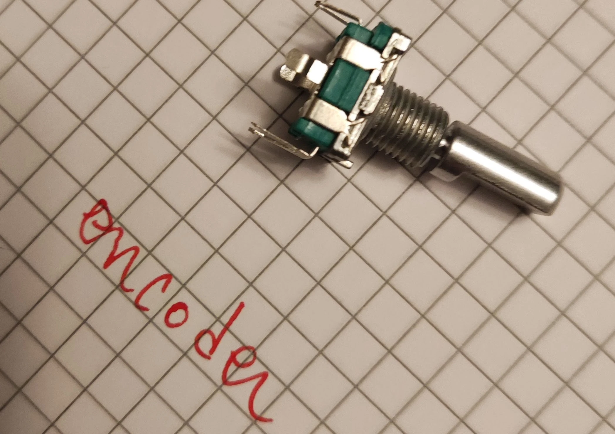
carefully push the encoder in its place. there are 5 pin but only 3 are used (in some models rev9 and after all are used), solder all of them and also consider soldering the oval ones too...
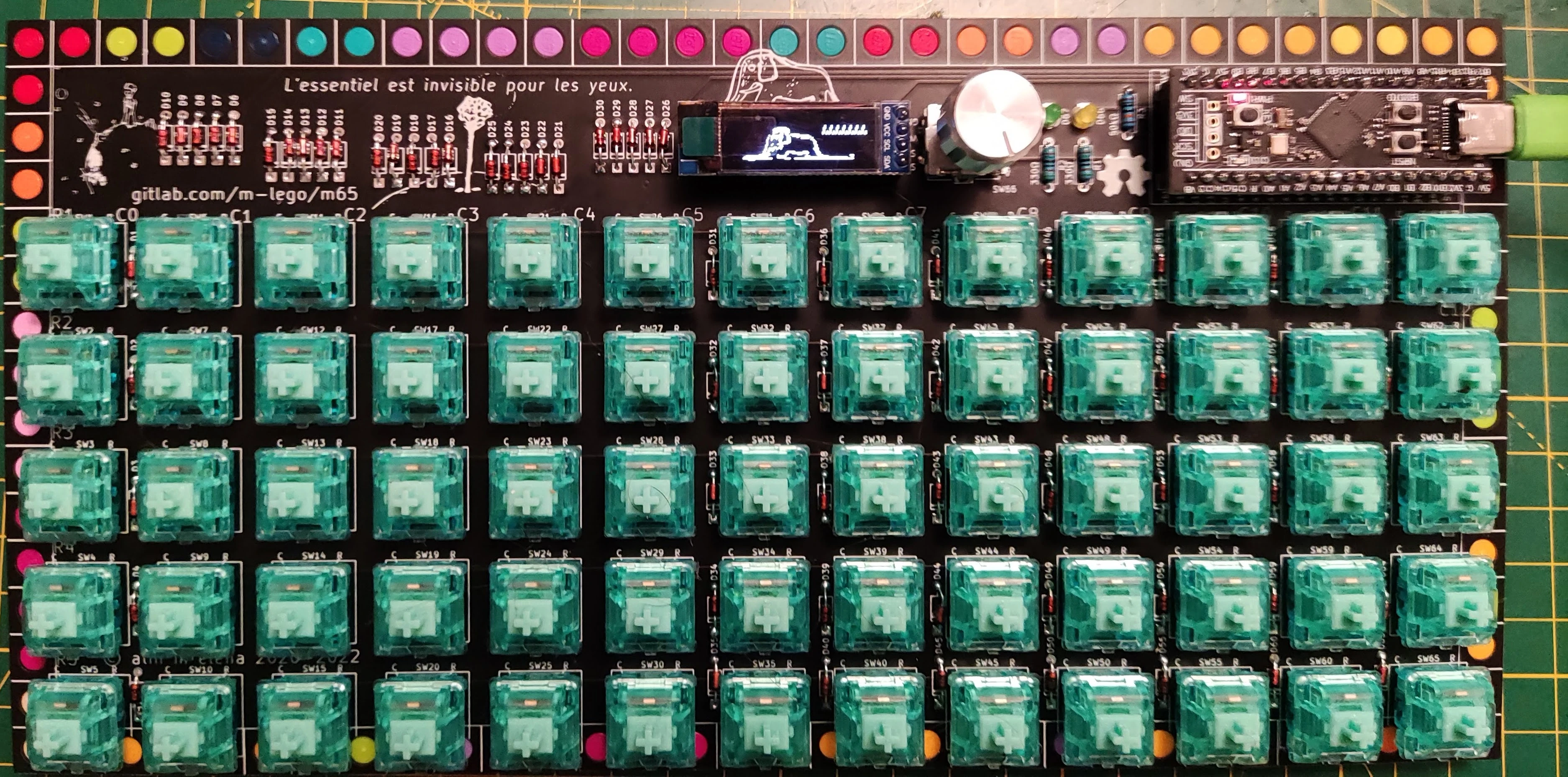
if all is ok now looks like this
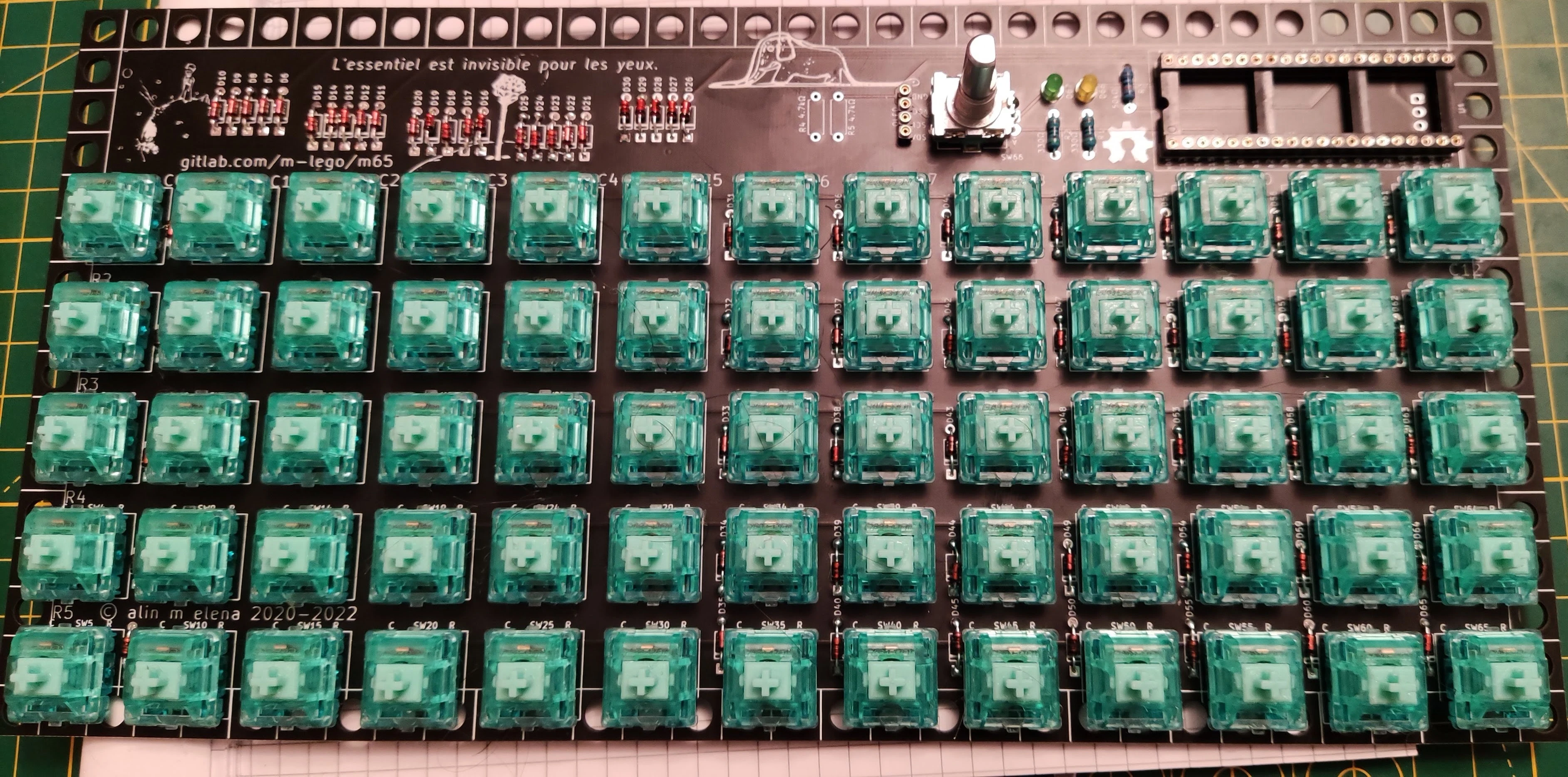
Success
at this point everything shall work..
the box
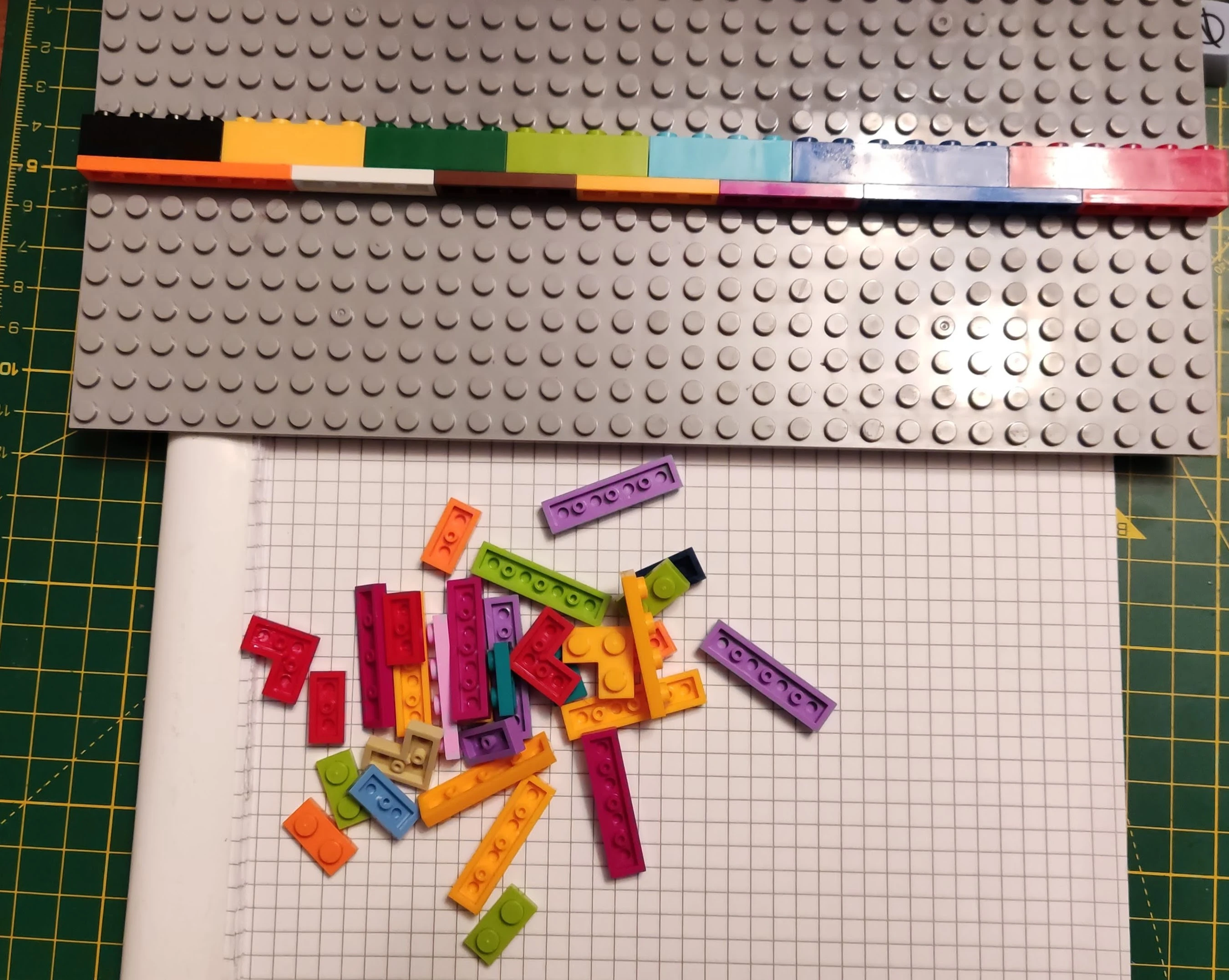
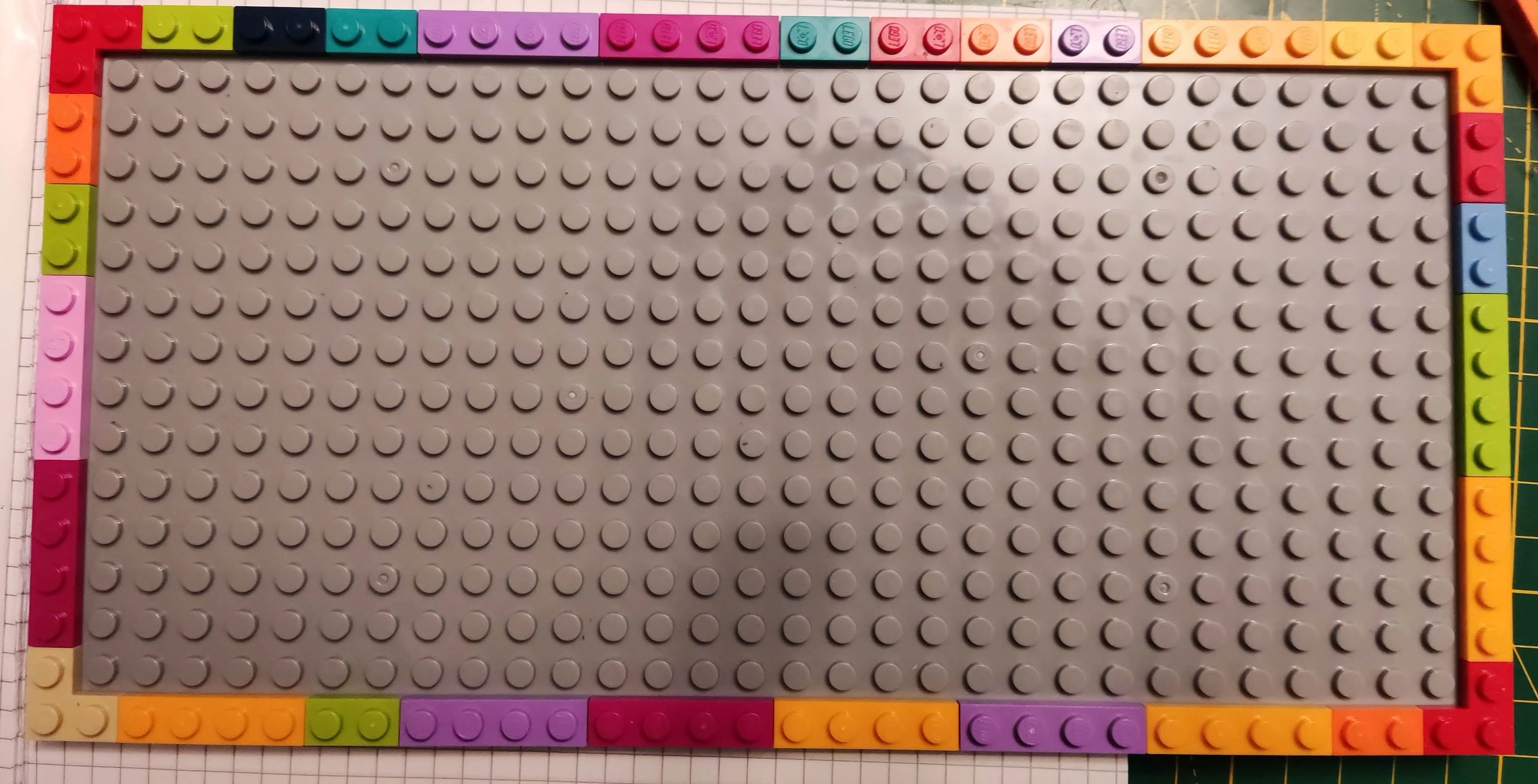
you can use a 16x32 plate or 2x16x16 plates and a mixture of lego plates, 1x2 and/or 1x4, corners if you have too. Also you can use a full brick and plate to give it a typing angle (around 6˚) already assembled in the picture above.
put it as you please
now you can put the pcb on top of the box base matching the lego inside. press gently till they are properly fit. thickness of the pcb is same as the lego prongs so you shall see them flush.
Warning
depending on the lego colours, plates sometimes you may notice a bend of the pcb. you will have to experiment with various colours for plates, nothing one cannot solve with lego.
now you can socket mcu, oled and the knob of the encoder and plug it in.
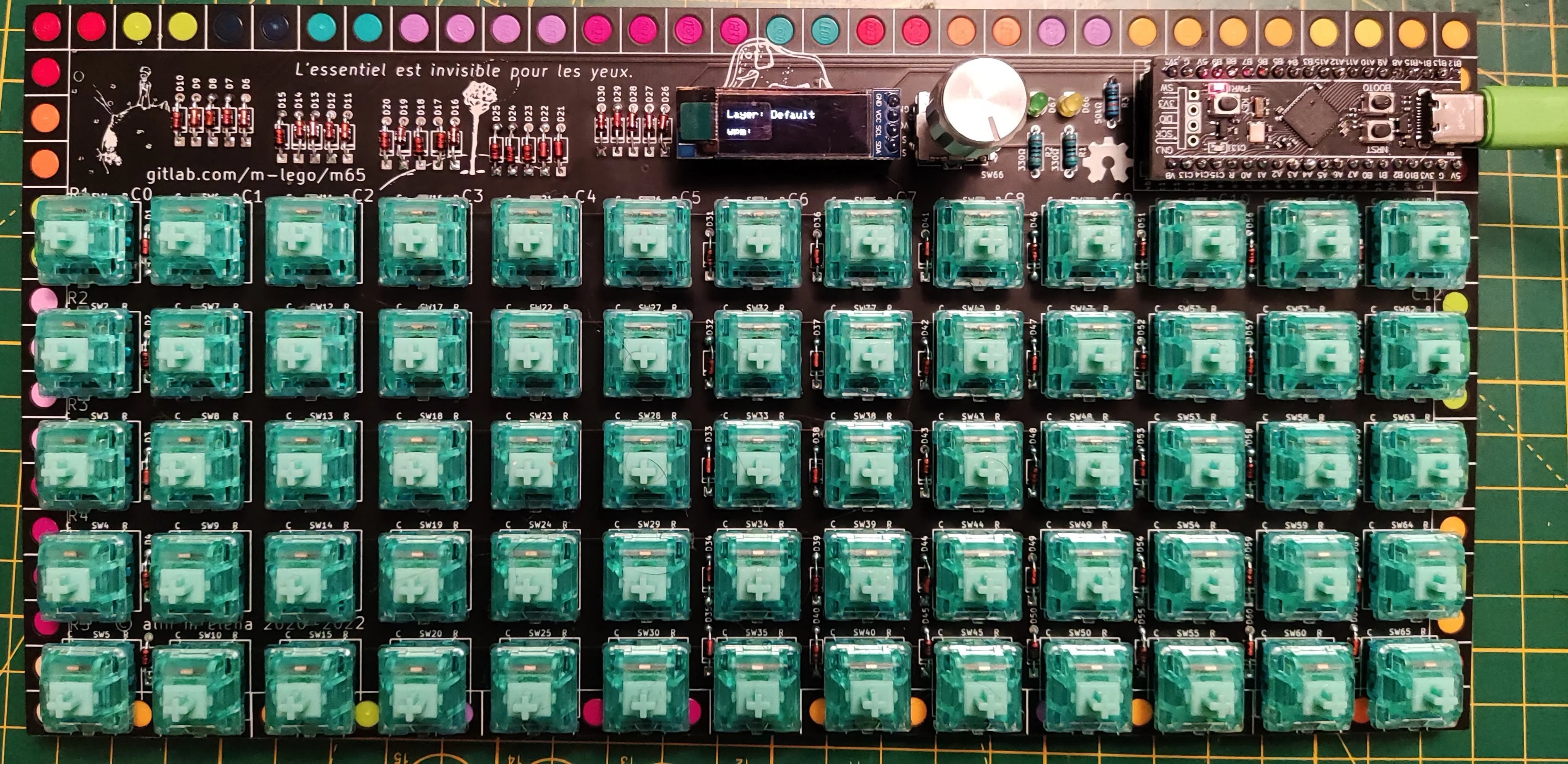
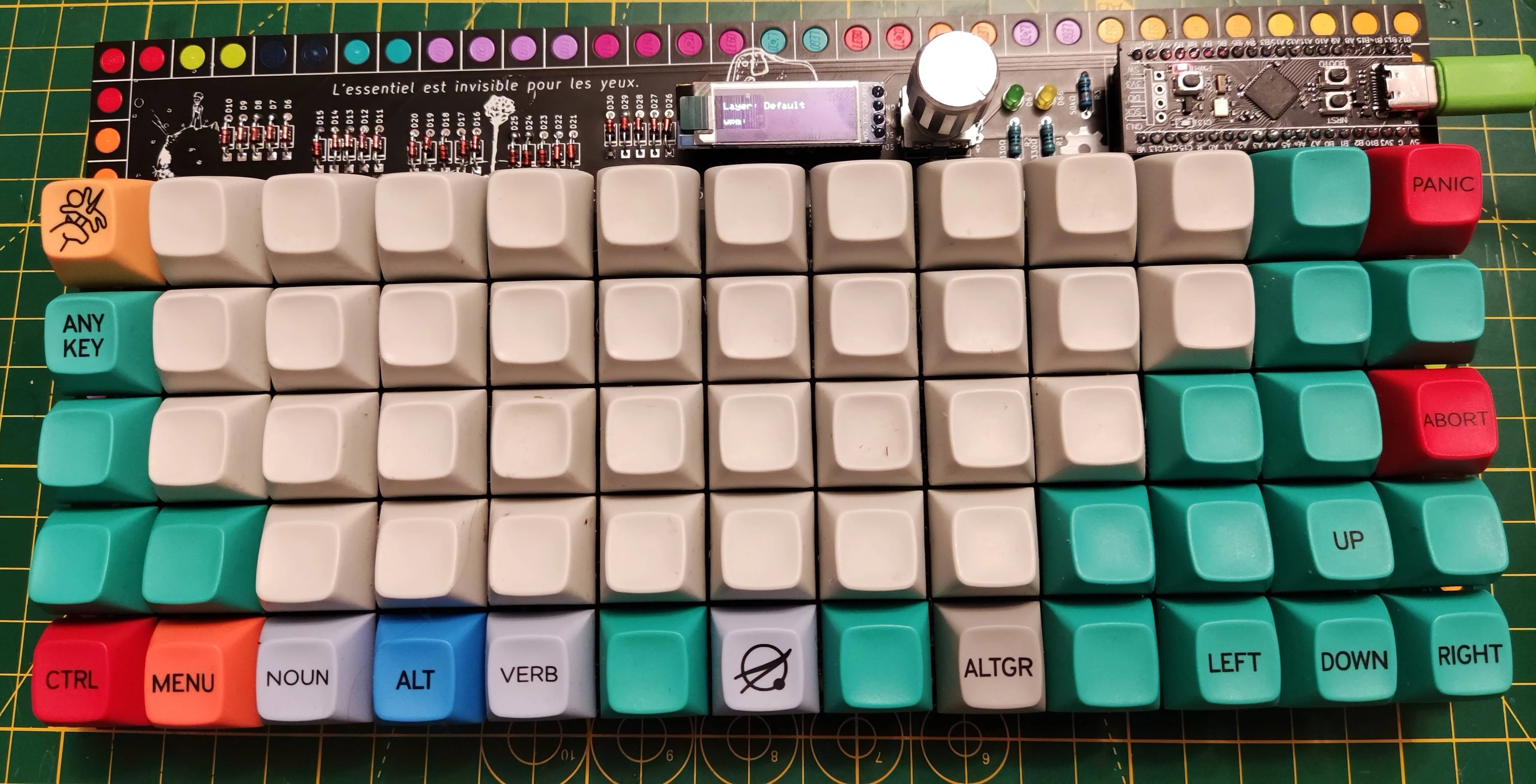
testing time
- if screen lights up showing an elephant inside a python it is perfectly fine. after few seconds, shall indicate you the the current layer and show wpm(some estimate of words per minute)
- encoder shall change the volume
- double tap dance the third key from the left on the bottom row, first led from the encoder shall be on... do it again shall be off...
- double tap dance the fifth key from the left on the bottom row, second led from the encoder shall be on... do it again shall be off...
- now you are ready to test the keys...
if anything goes wrong you will need to debug... otherwise put the keycaps and enjoy.