m65
m65 - the lego keyboard
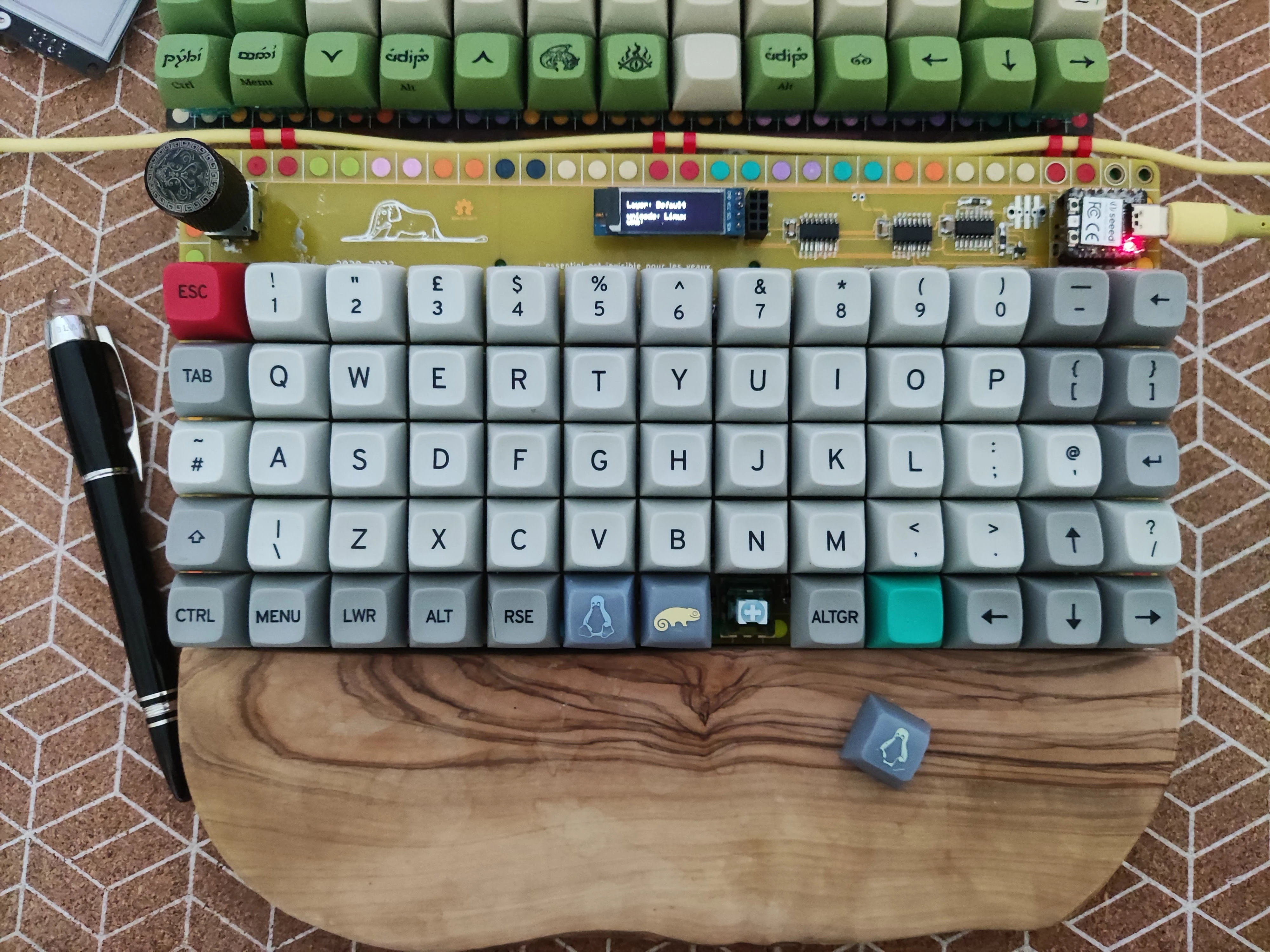
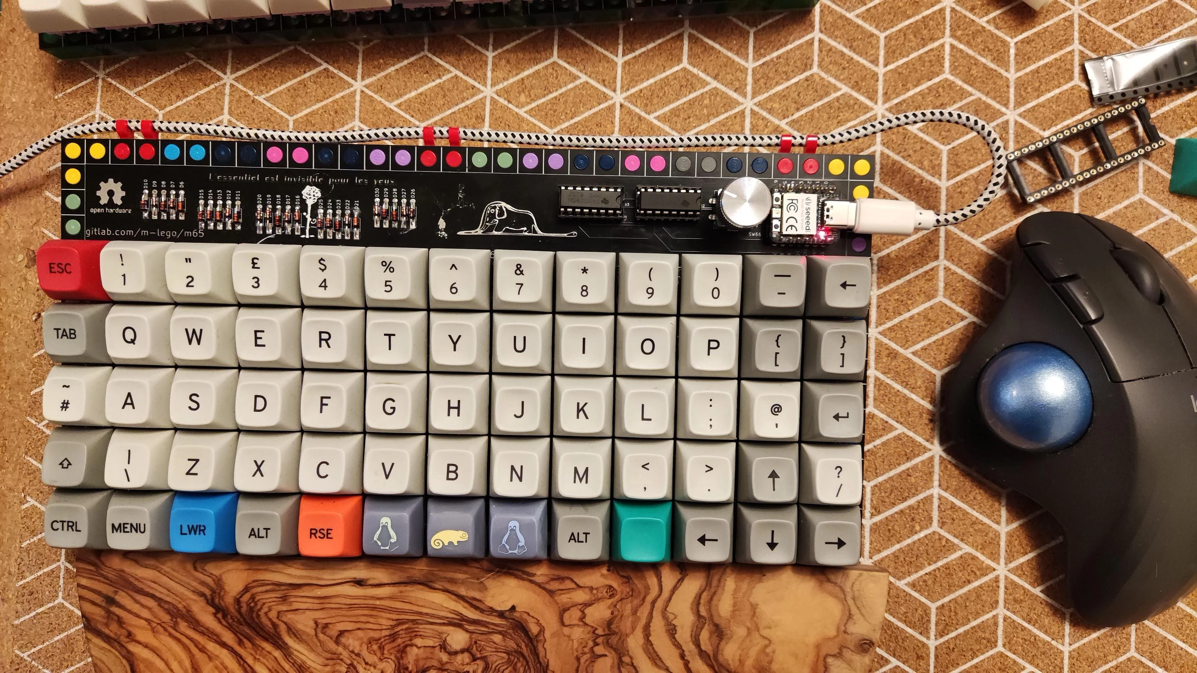
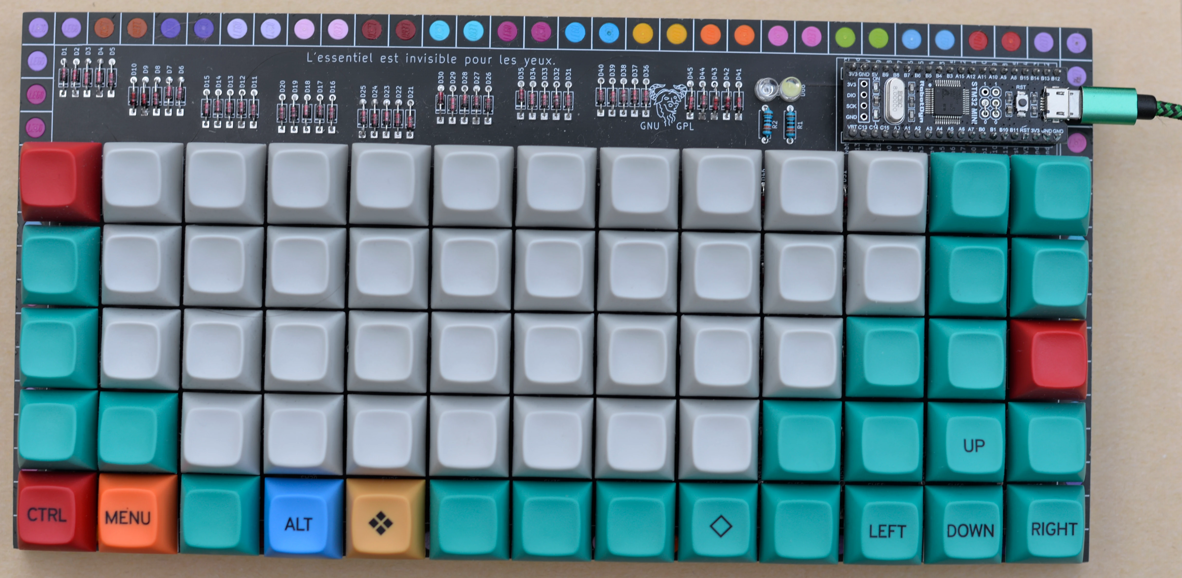
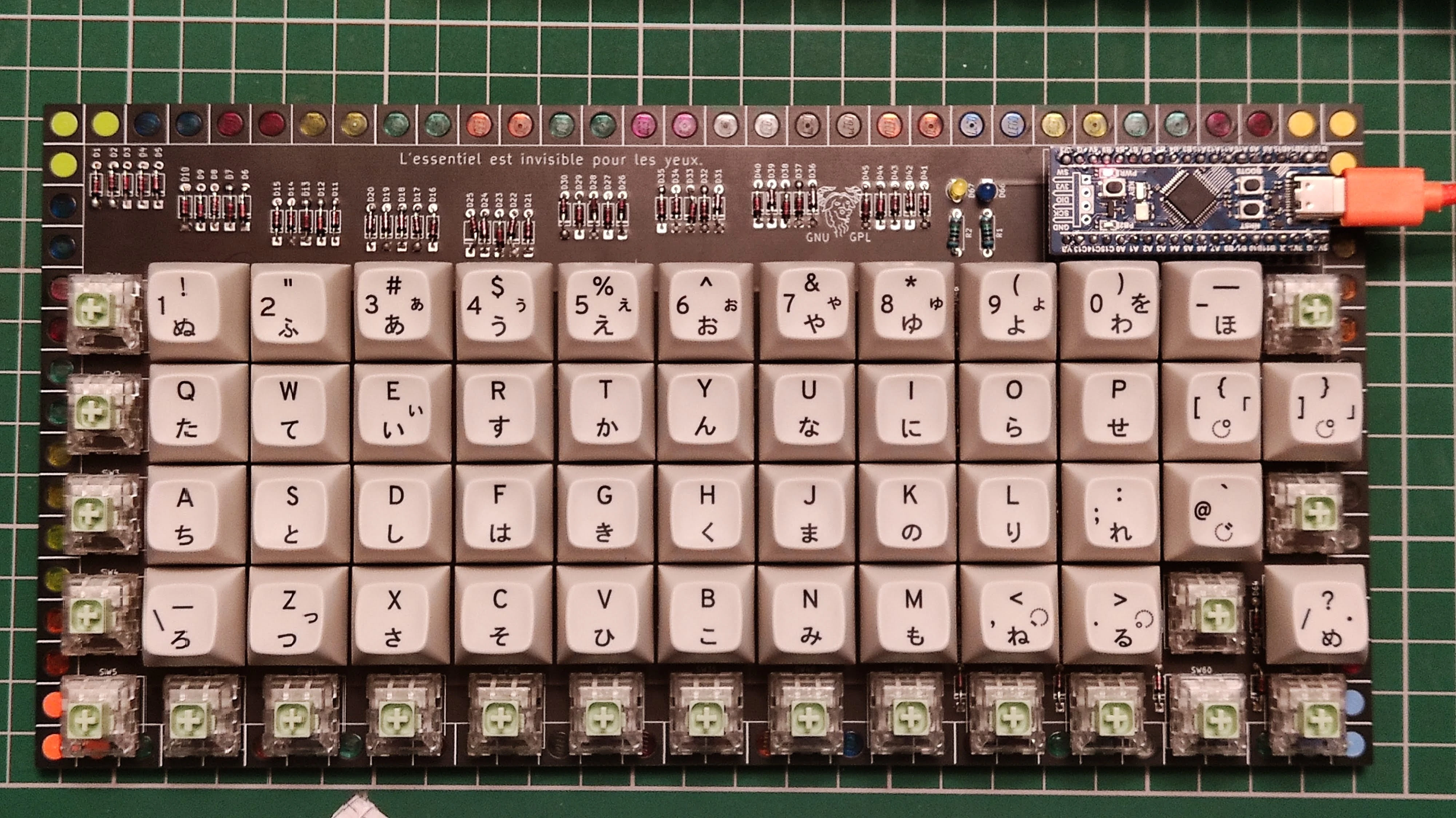
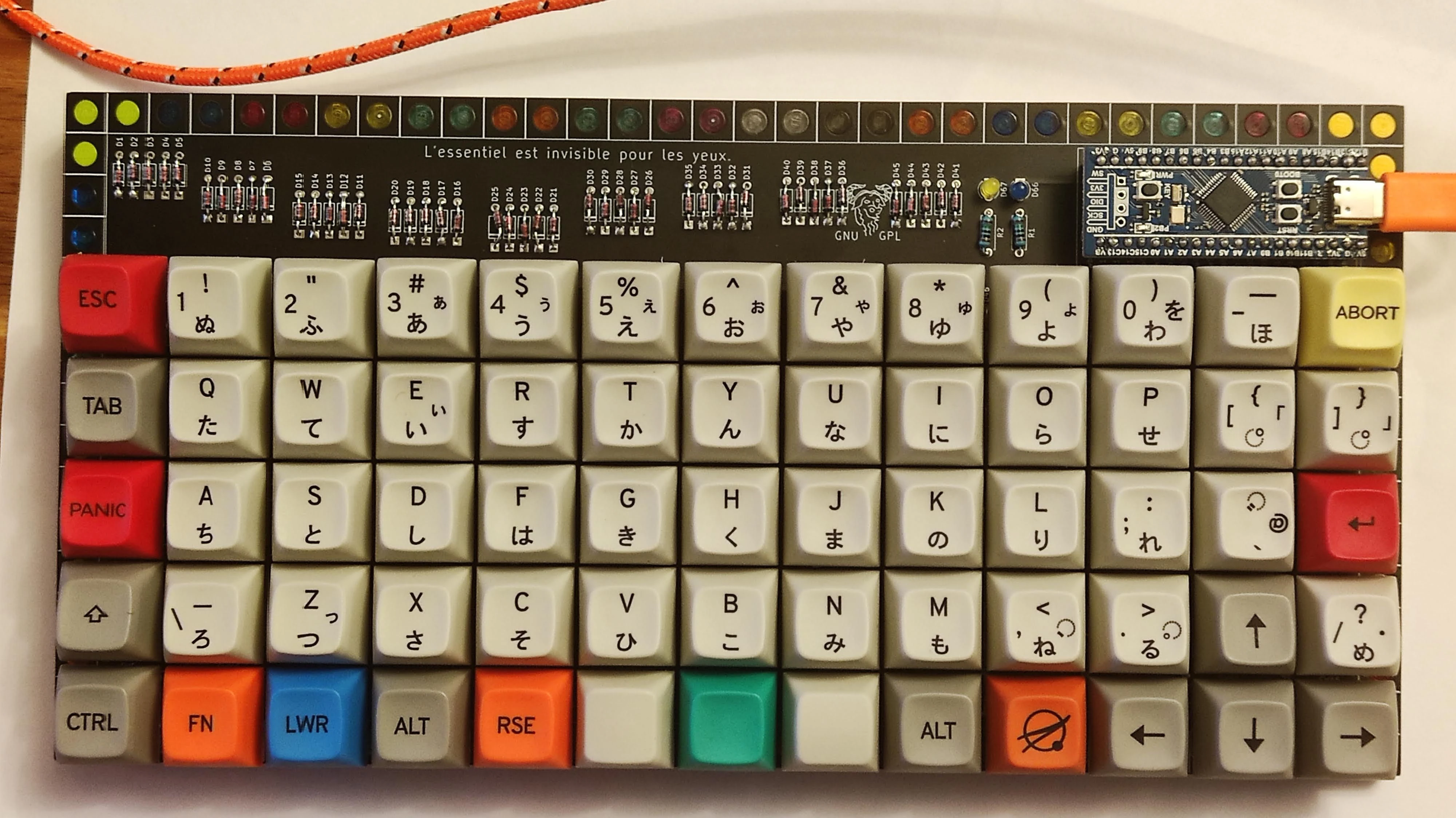
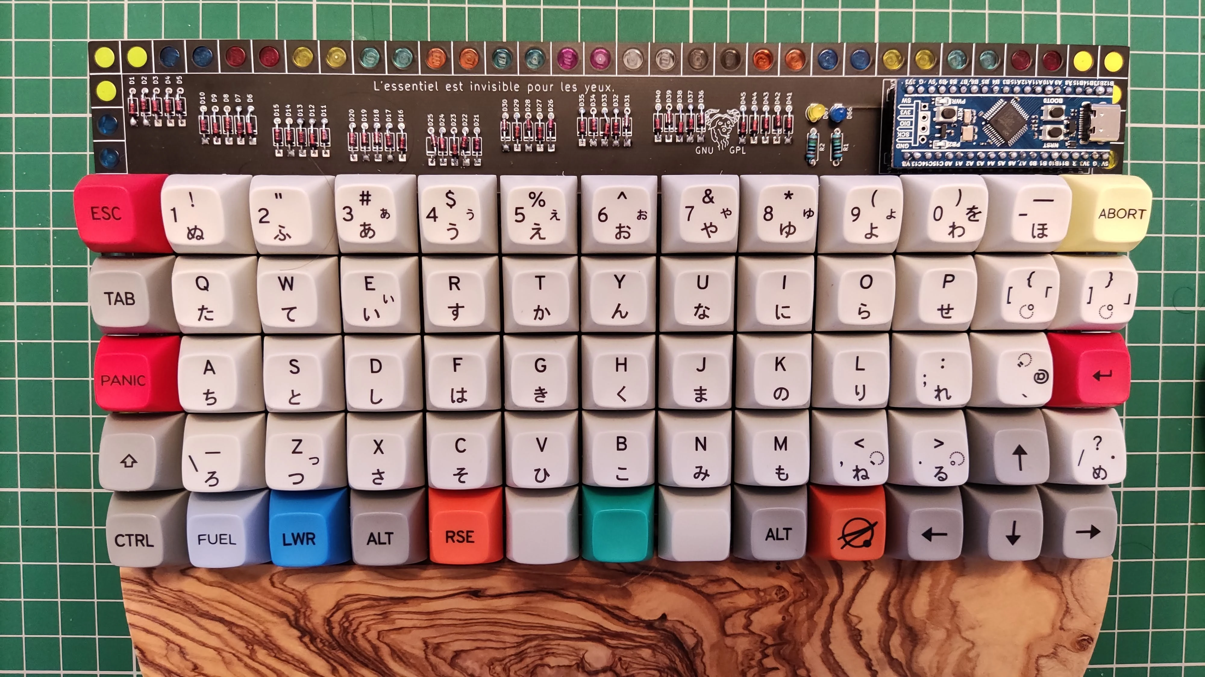
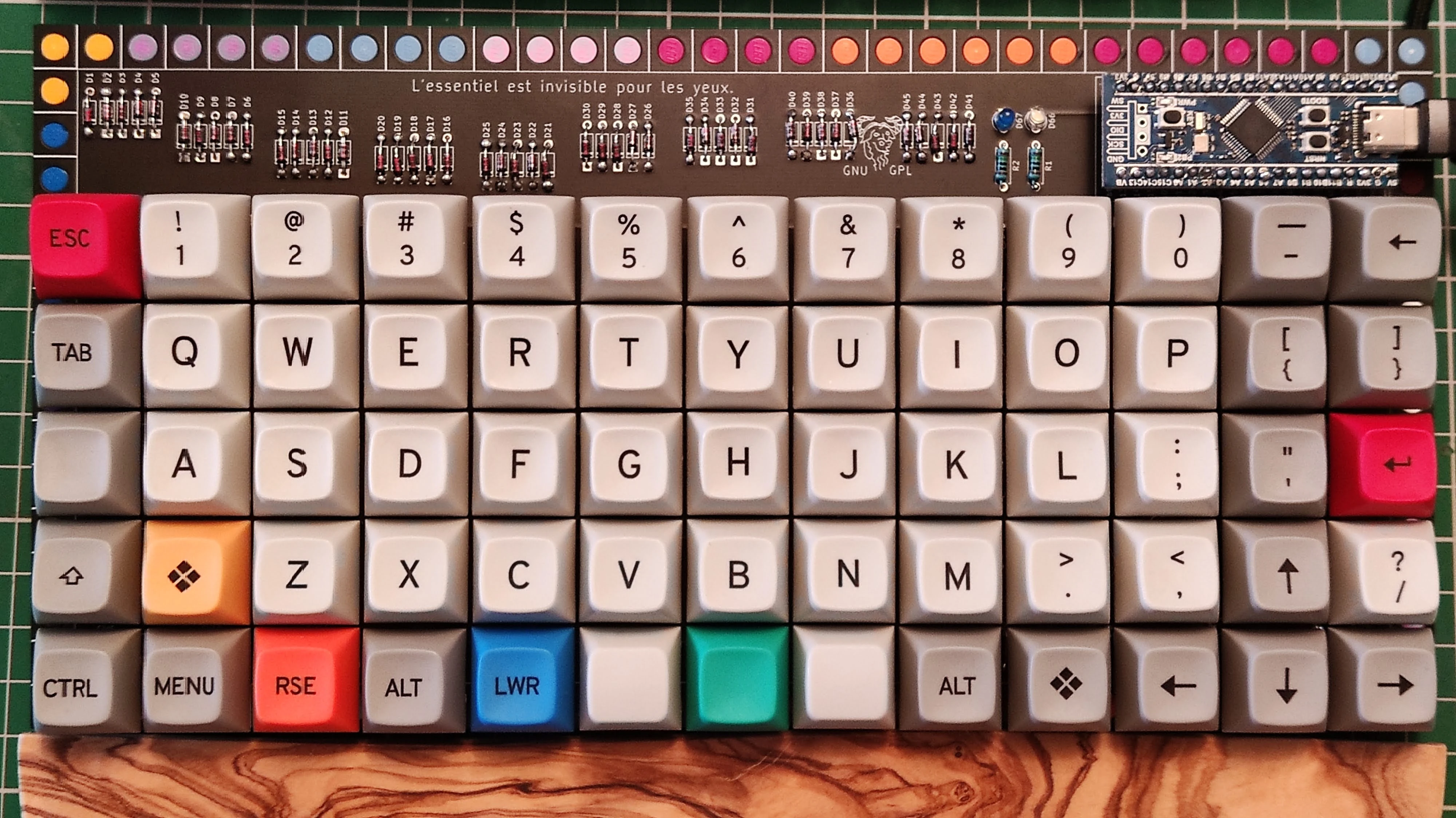
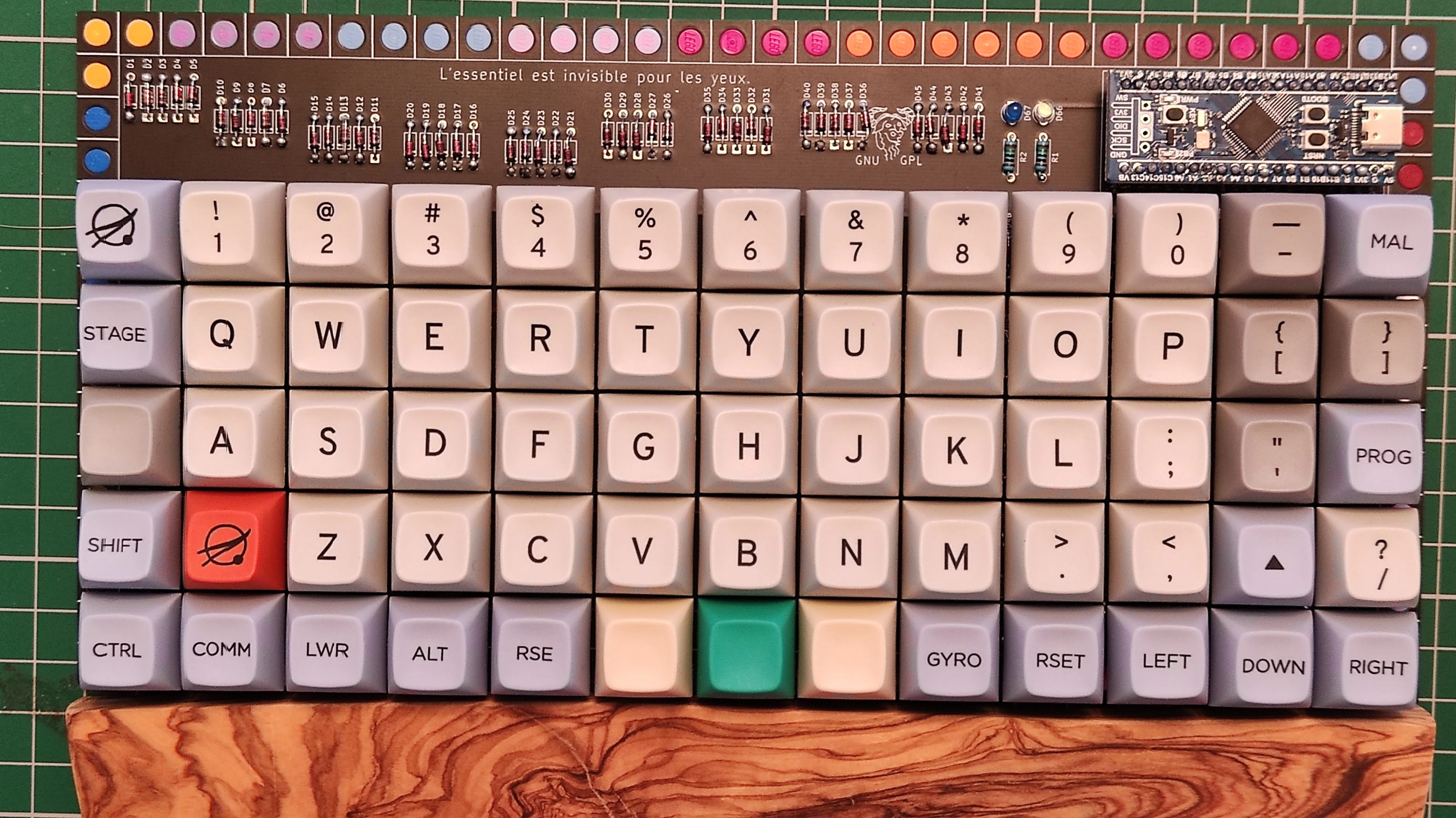
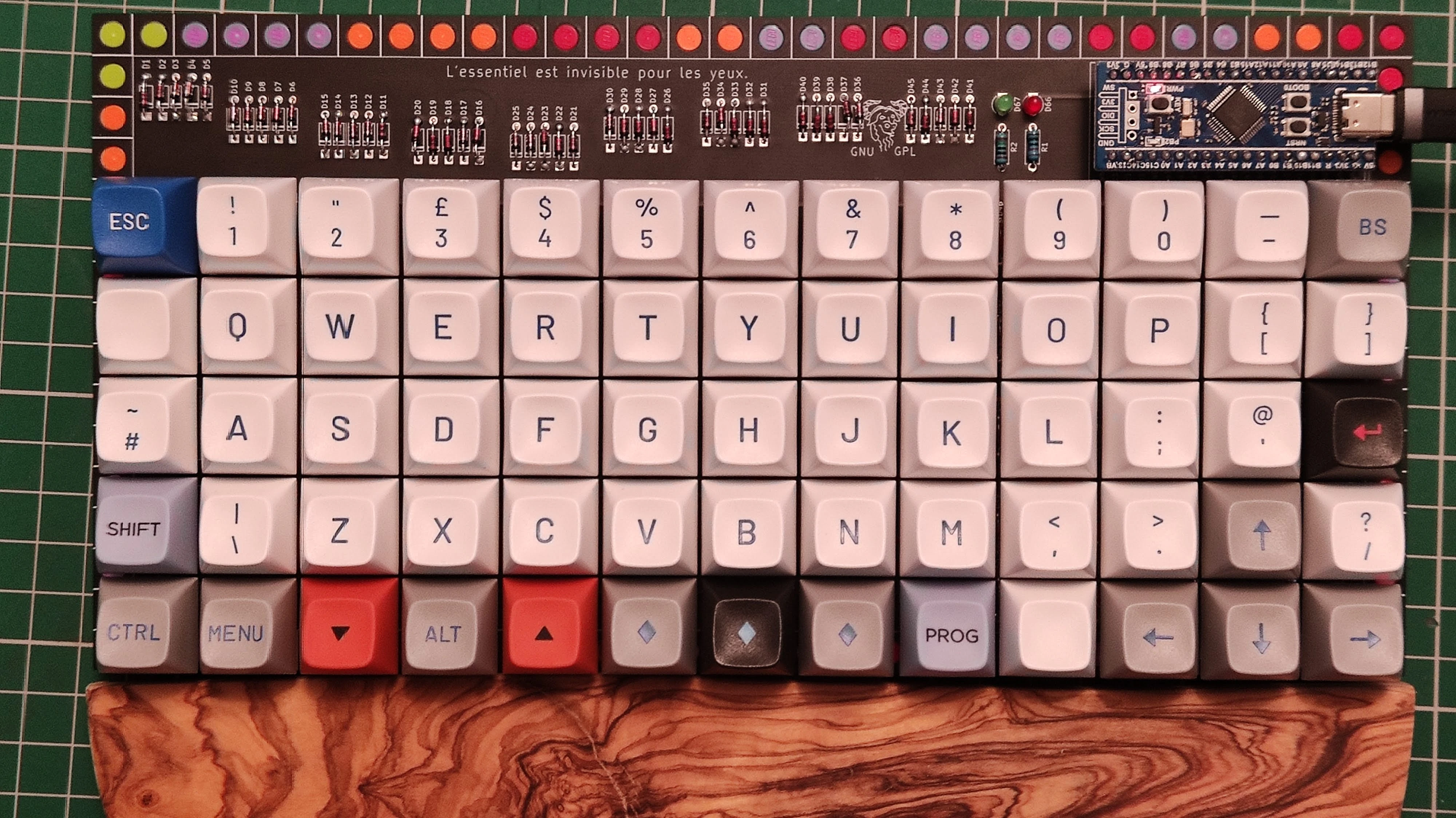
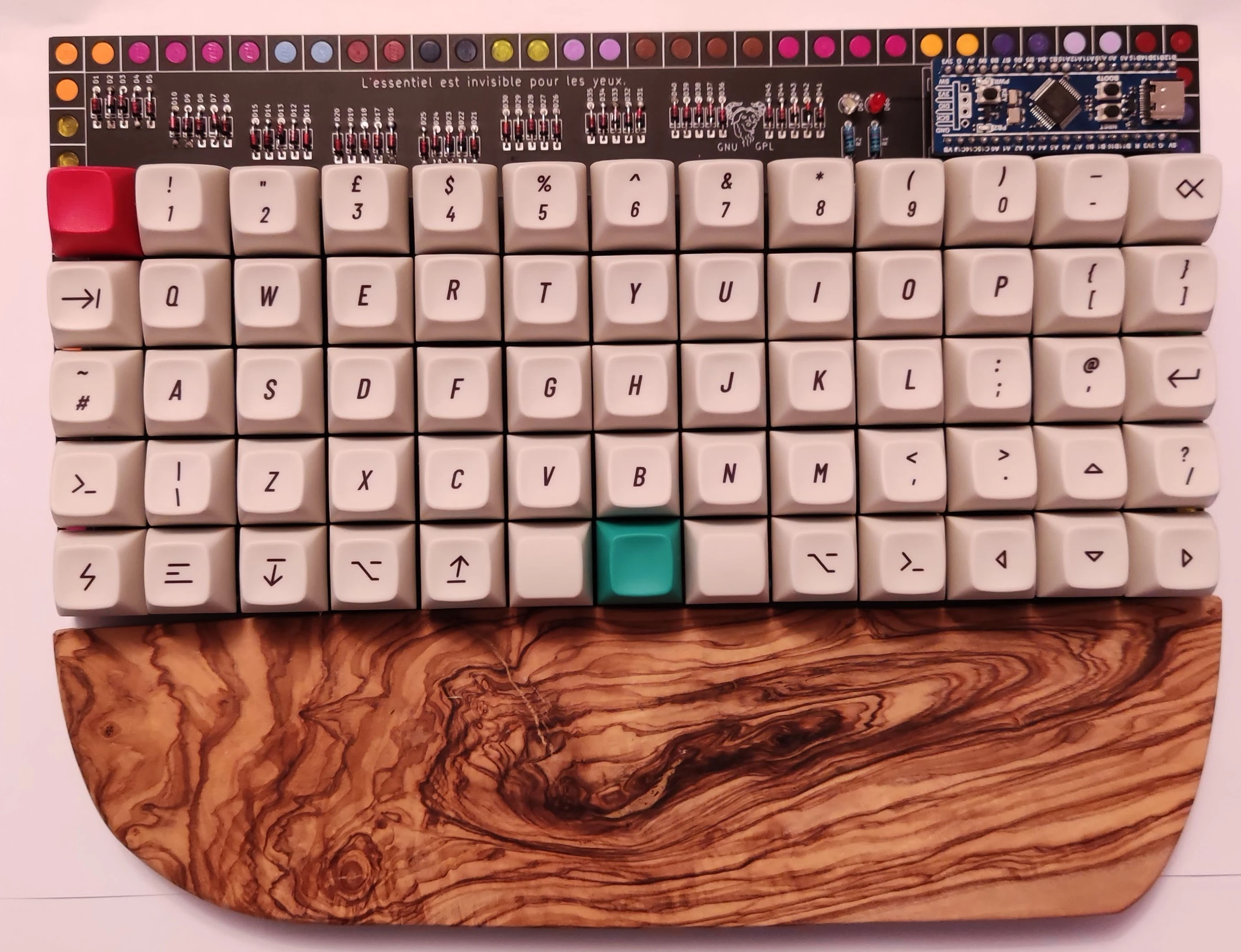
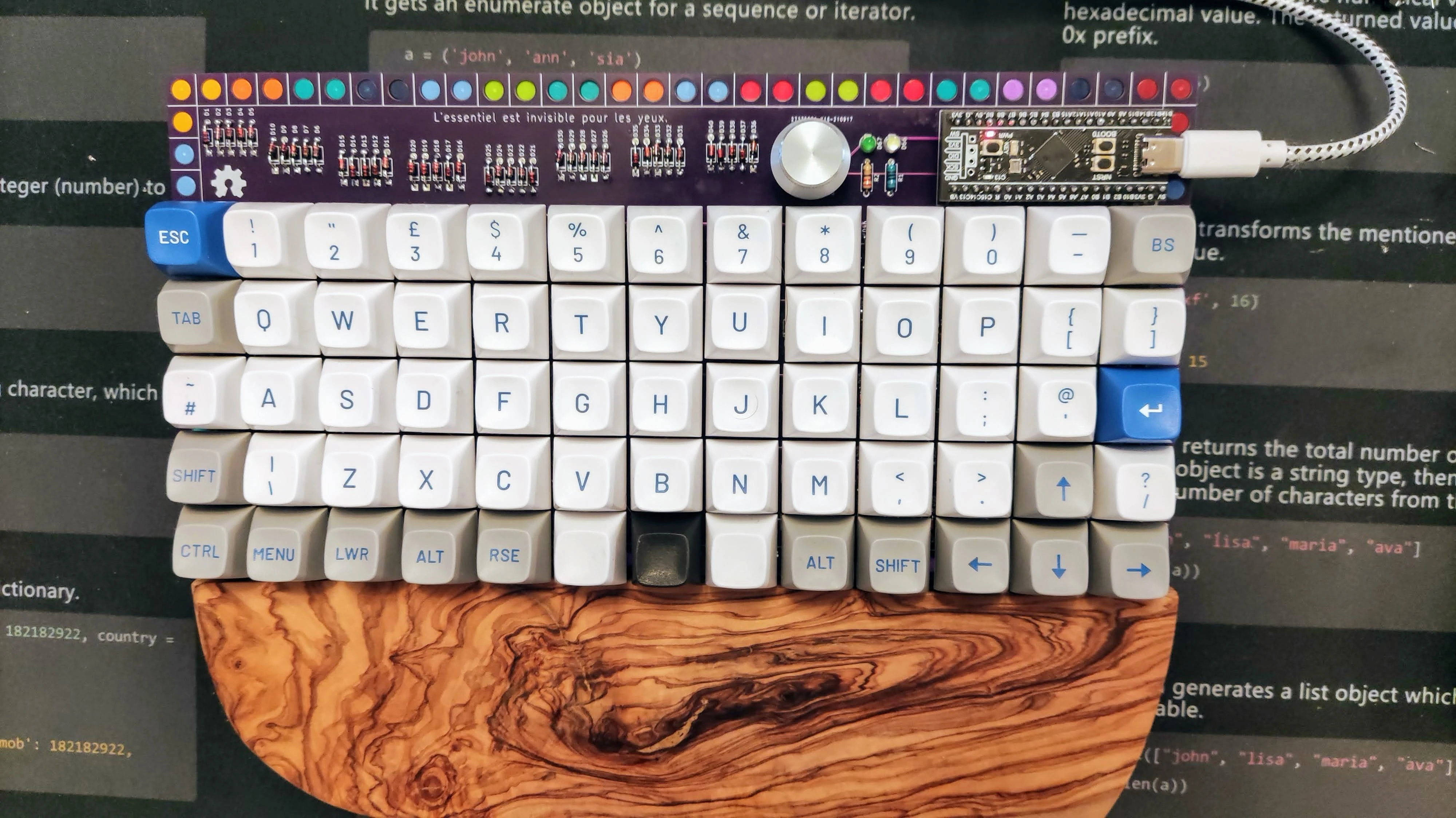
this is a 5 rows 13 columns ortholinear keyboard intented to allow all the keycaps that you will find on an iso layout.
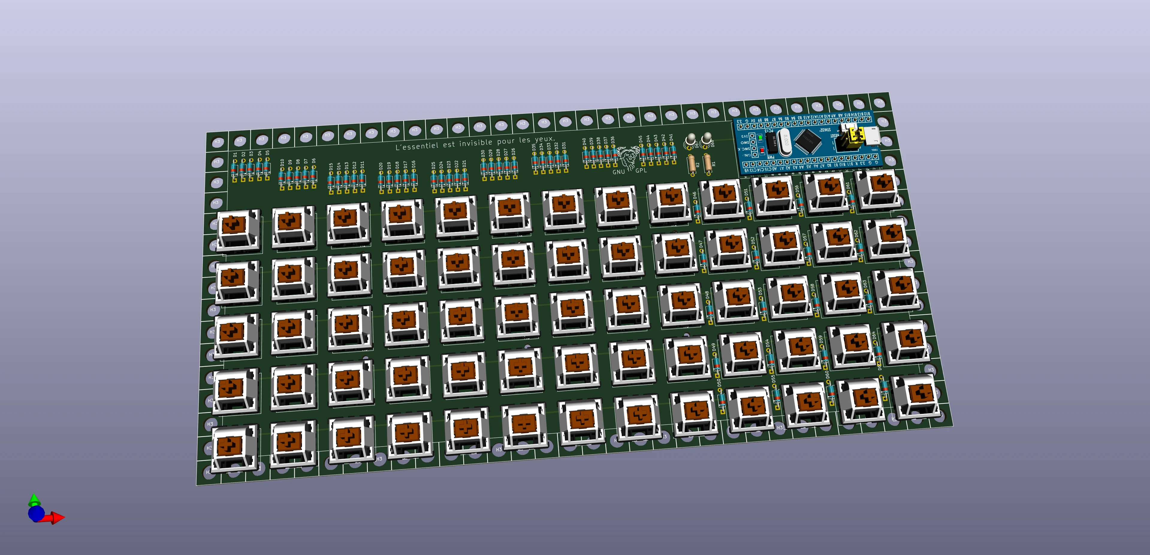
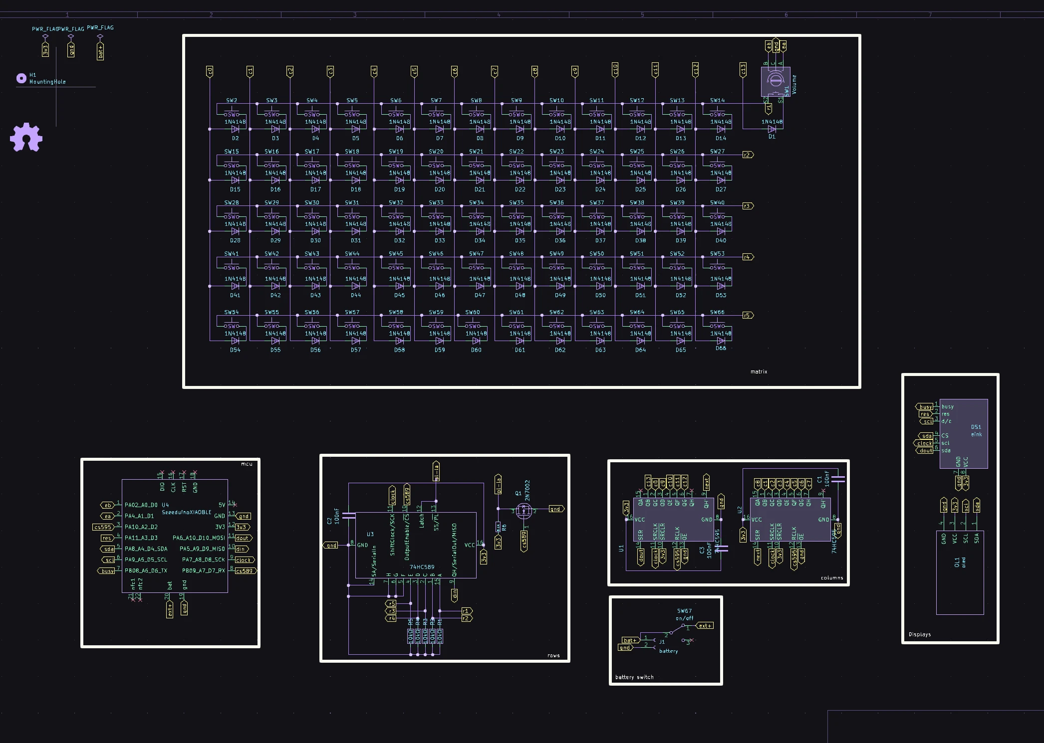
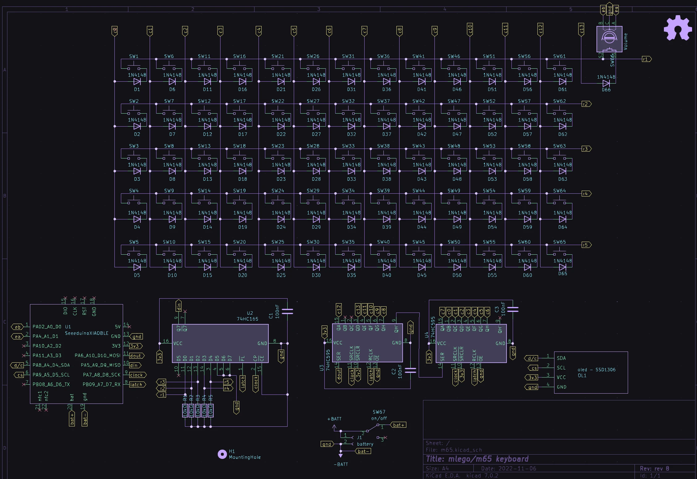
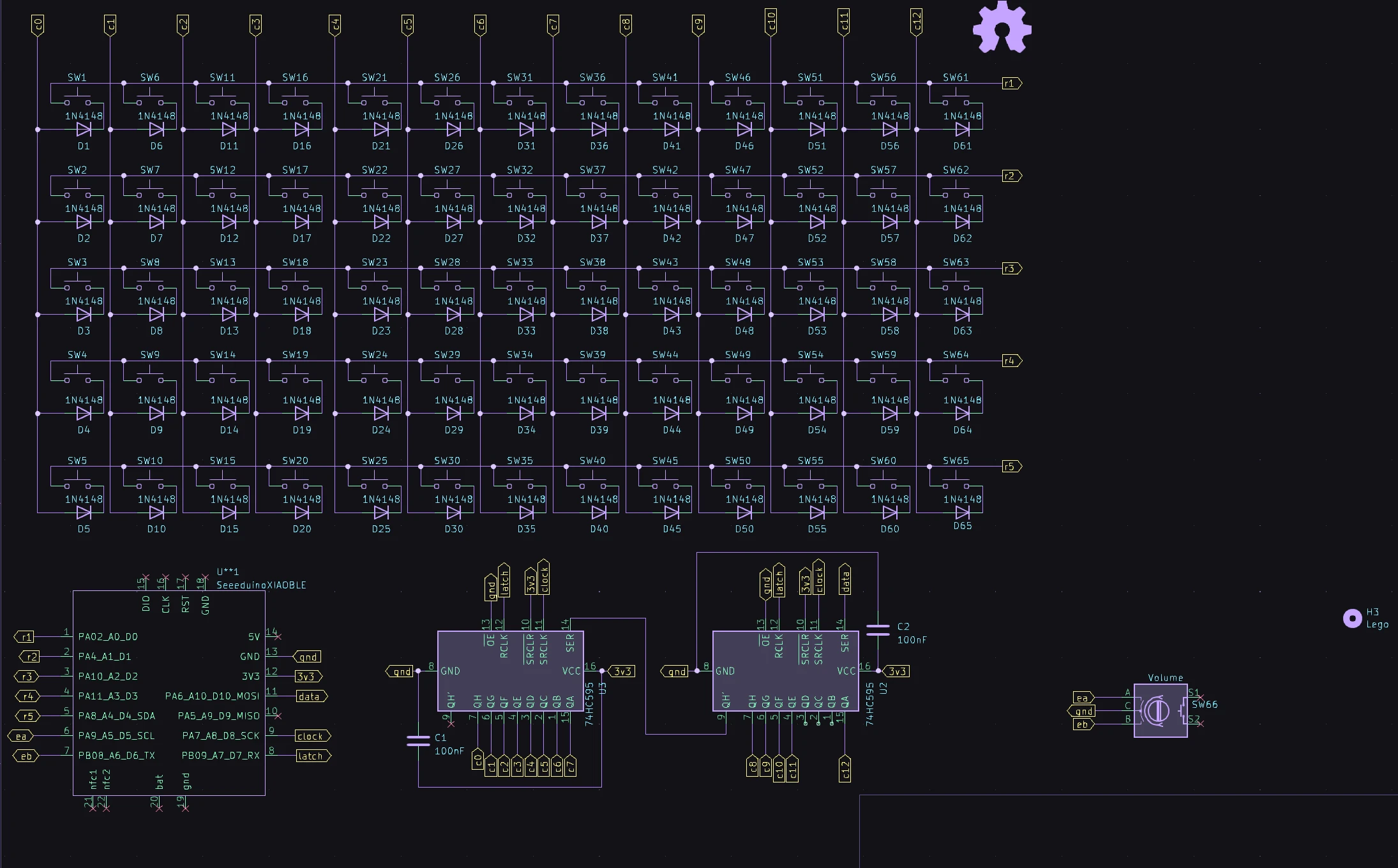
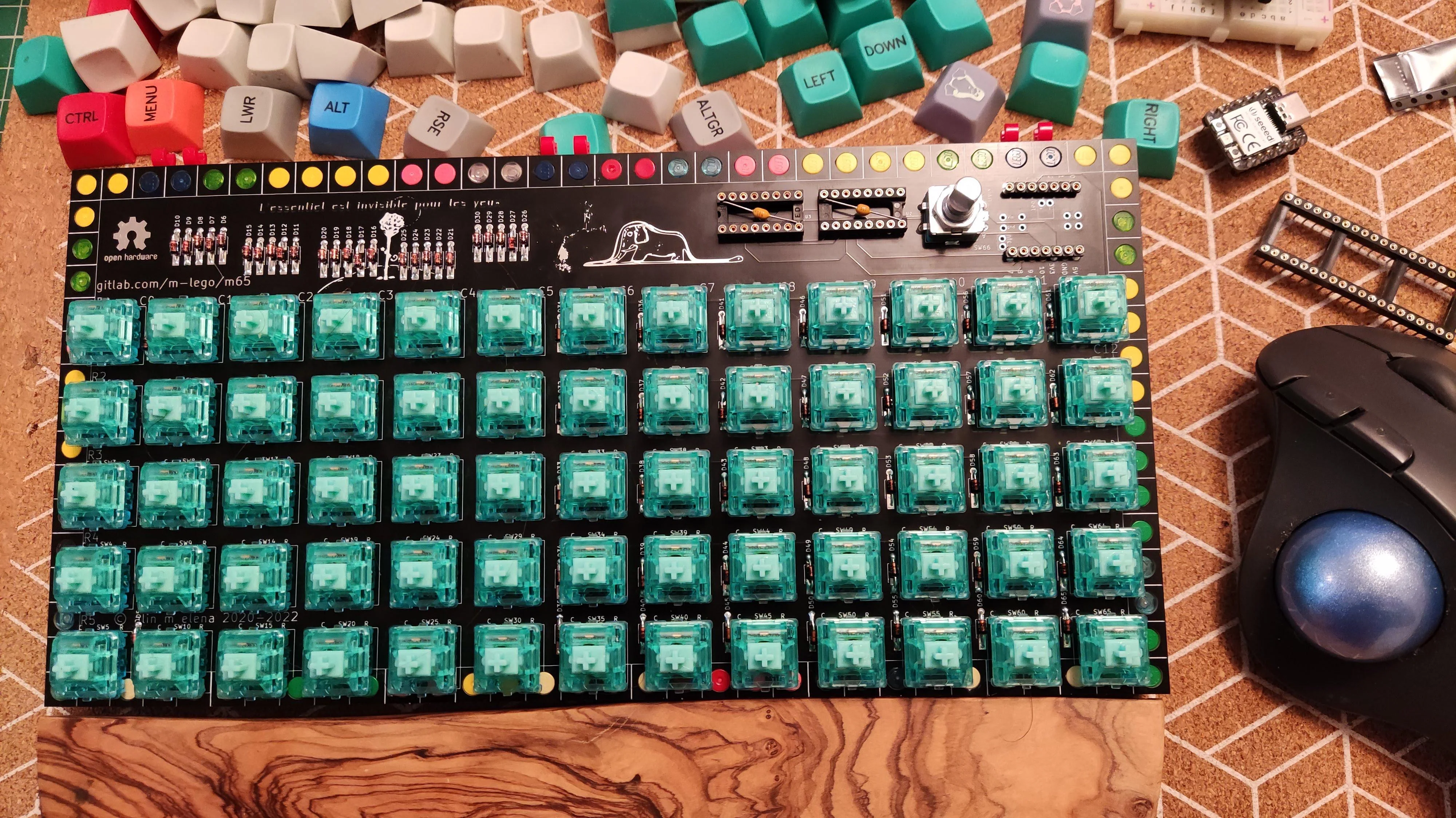
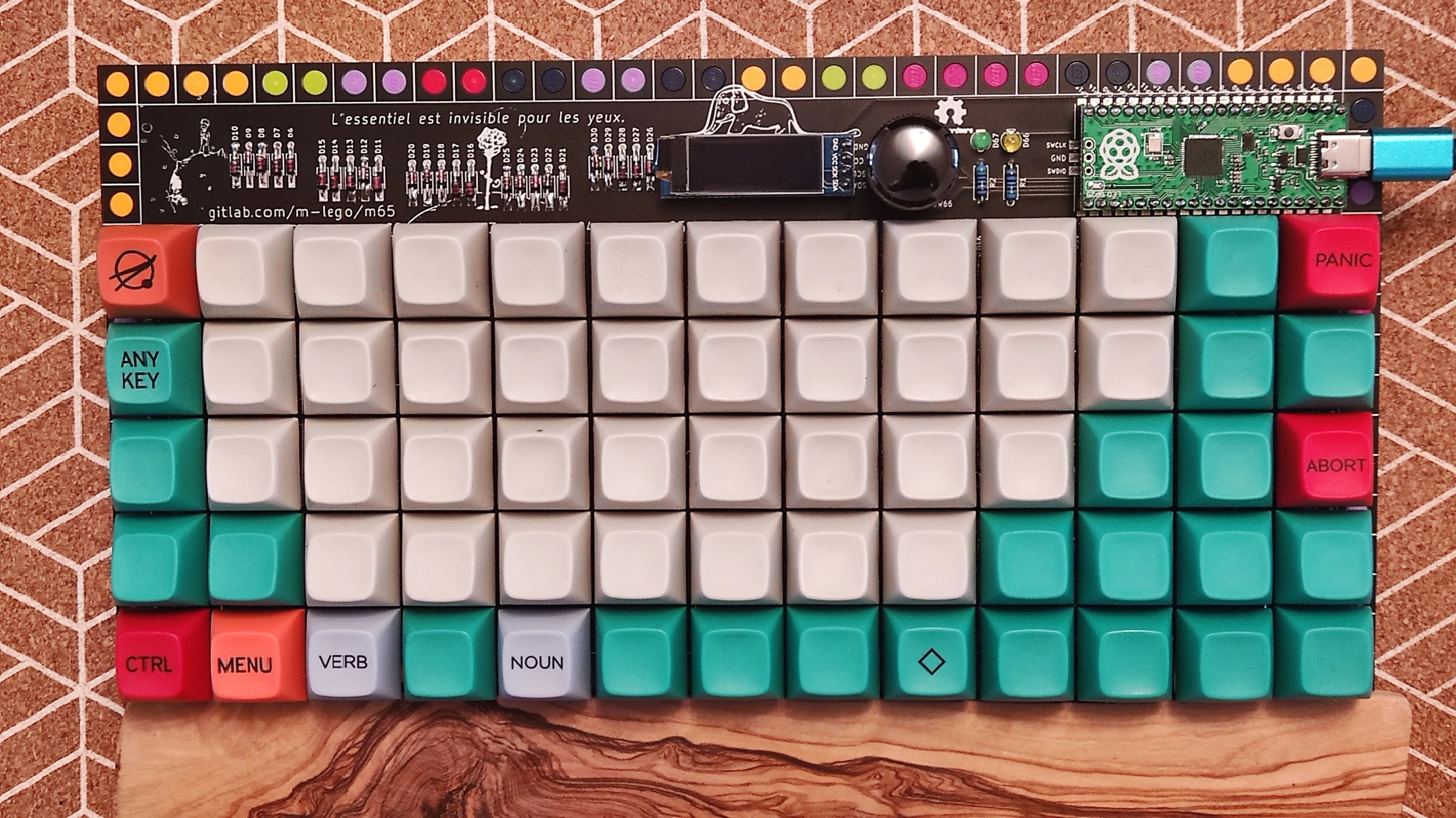
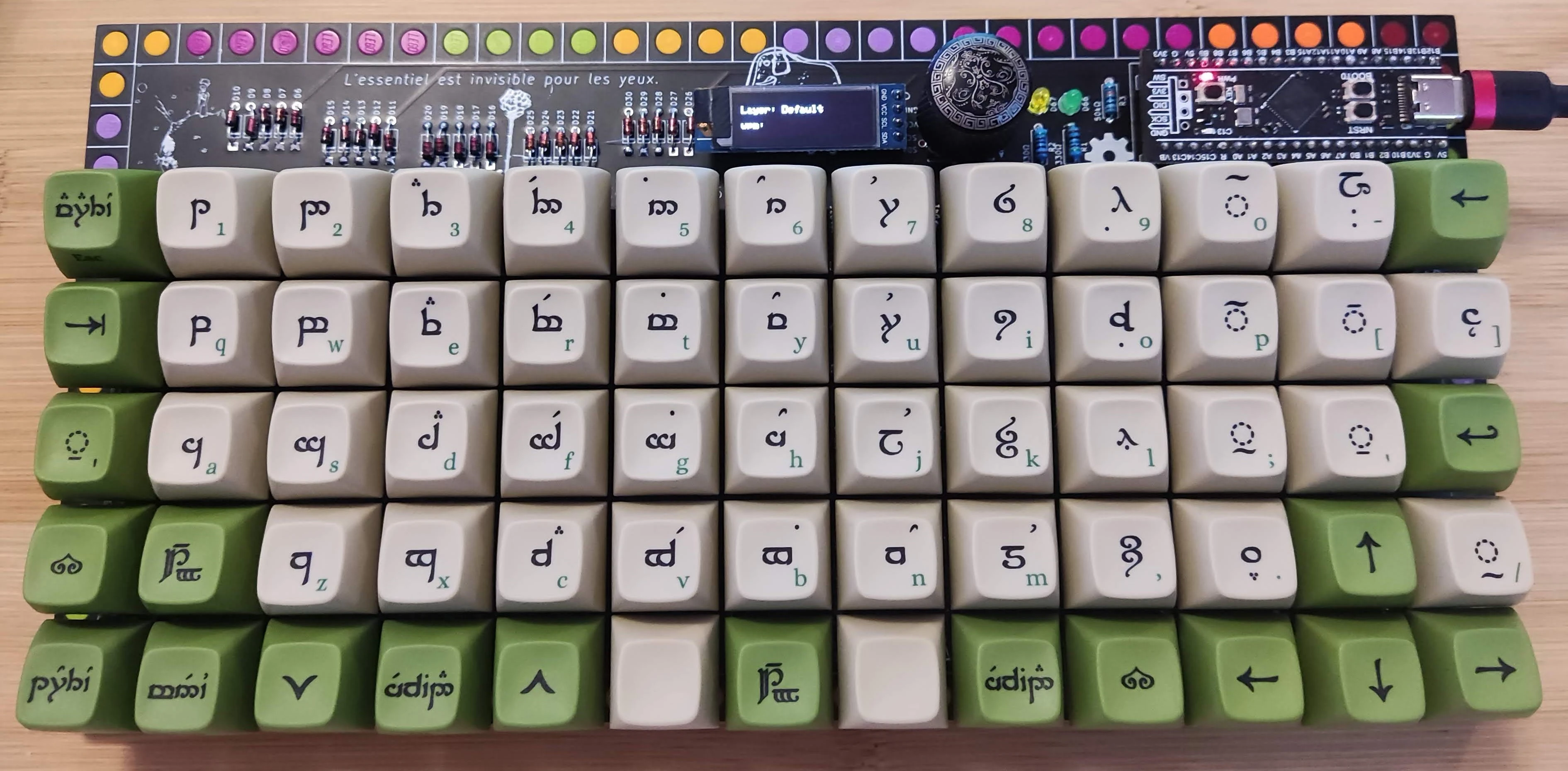
current iteration... this is a departure from the normal matrix keyboard. I am using seeed studio xiao rp2040 or seeed studio xiao nrf52840 (probably samd21 will work too but I have none to test) and also play with zmk as firmware since I was curious on bt. Since xiao does not have enough pins for the full matrix... The approach I use is, rows are read from one shift register HC589 while columns use 2 HC595 shift registers chained, oled and rotary encoder. Please note the shift register use the SPI, sharing clock and latch pins. The rotary encoder now supports the push button too, which makes it technically a 14 columns ortho.
Please note that I am aware of the xiao contest for mechanical keyboards and their fusion pcb assembly service. For rev7, seeed studio kindly agreed to sponsor 5x13 version with pcbs and MCUs.
status: rev 11 done and tested
- gerbers designed
- firmware
- breadboard tested
- gerbers printed
- board tested
revisions
- rev11 xiao rp2040 with 3 shift registers 2xHC595 and 1xHC589, oled/eink(ssd1680 weact) and push rotary encoder with qmk ( actively looking into zmk firmware support for both rp2040 and nrf52840)
- rev10 xiao rp2040 with 3 shift registers 2xHC595 and 1xHC589, oled and push rotary encoder with qmk ( actively looking into zmk firmware support for both rp2040 and nrf52840)
- rev9 xiao rp2040 with 3 shift registers 2xHC595 and 1xHC165, oled and push rotary encoder with qmk ( actively looking into zmk firmware support for both rp2040 and nrf52840)
- rev7/8 xiao rp2040 and nrf52840 with 2 shift registers HC595, rotary encoder and no oled, for rp2040 version both qmk and zmk firmware
- rev5/rev6 - rp2040 support, rpico, weact and other compatible clones, encoder non push, oled
- rev4 stm32f401/411, encoder non push , oled,
- rev3 stm32f401/411, encoder non push
- rev2 GD32F303 aka bluepill plus, usb C f103 equivalent, https://github.com/WeActStudio/BluePill-Plus
- rev1 STM32F103/APM32F103 or stm32f303
bom
mcus
Warning
i used few mcus over the time based on some reference boards. this makes life easier to design a keyboard since all the complicated electronics is on the mcu board. it is a great way to get into diy keyboards. while I have done handwire projects with avr, atmega32u4 i strongly advise against using them.
- rev1, stm32f103 aka bluepill. https://stm32-base.org/boards/STM32F103C8T6-Blue-Pill.html there were and maybe still around versions with black pcb.
- rev1, stm32f103 blackpill robotdyn do not confuse with f401/411 blackpill from weact https://stm32-base.org/boards/STM32F303CCT6-RobotDyn-Black-Pill.html
both these are great nice little boards, unfortunately they are micro usb and need you to burn a stm32duino bootloader on them.
-
rev2 GD32F303, aka bluepill plus, is a bluepill with a type c usb. https://github.com/WeActStudio/BluePill-Plus
-
rev3/rev4 stm32f401/411 weact blackpill, https://github.com/WeActStudio/WeActStudio.MiniSTM32F4x type c
- rev5/rev6 rp2040, raspberry pi pico and comptatible, https://www.raspberrypi.com/documentation/microcontrollers/raspberry-pi-pico.html original pico is usb micro, one can buy type c variants from aliexpress but needs to be careful the pins match. waveshare version is a very nice compatible and improved version https://www.waveshare.com/wiki/RP2040-Plus or a cheaper version if you find.
all above boards have enough pins not to need any magic to get you a nice keyboard
- rev7/rev9/rev10/rev11 rp2040, xiao rp2040, https://wiki.seeedstudio.com/XIAO-RP2040/ very small nice board.... due to size not a lot of pins exposed so i moved away from some simple electronics.
all the mcus are qmk compatible rev7 and hopefully soon rev9 support zmk
-
rev7/rev9 xiao nrf52840 https://wiki.seeedstudio.com/XIAO_BLE/, zmk only for rev9 you may need a special version of zmk, see in their discord
-
if you need more pins you can try stm32g431 from weact https://github.com/WeActStudio/WeActStudio.STM32G431CoreBoard qmk supports it already.
rev 11
revision 11
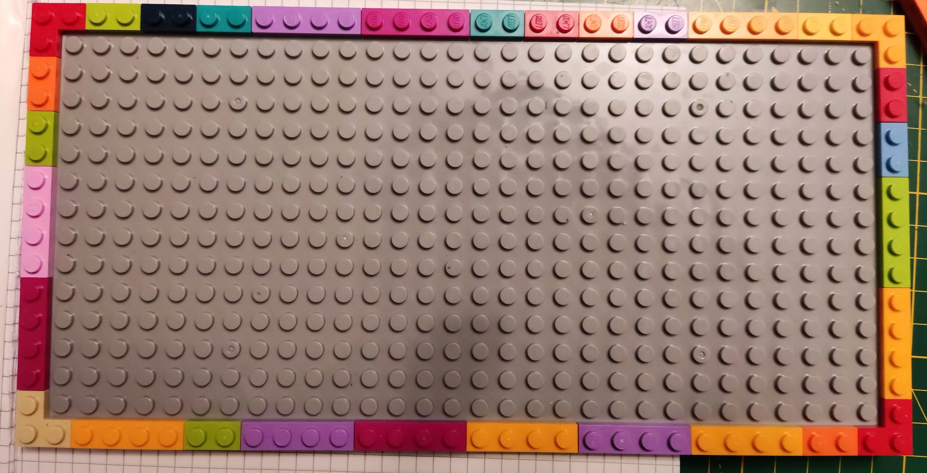
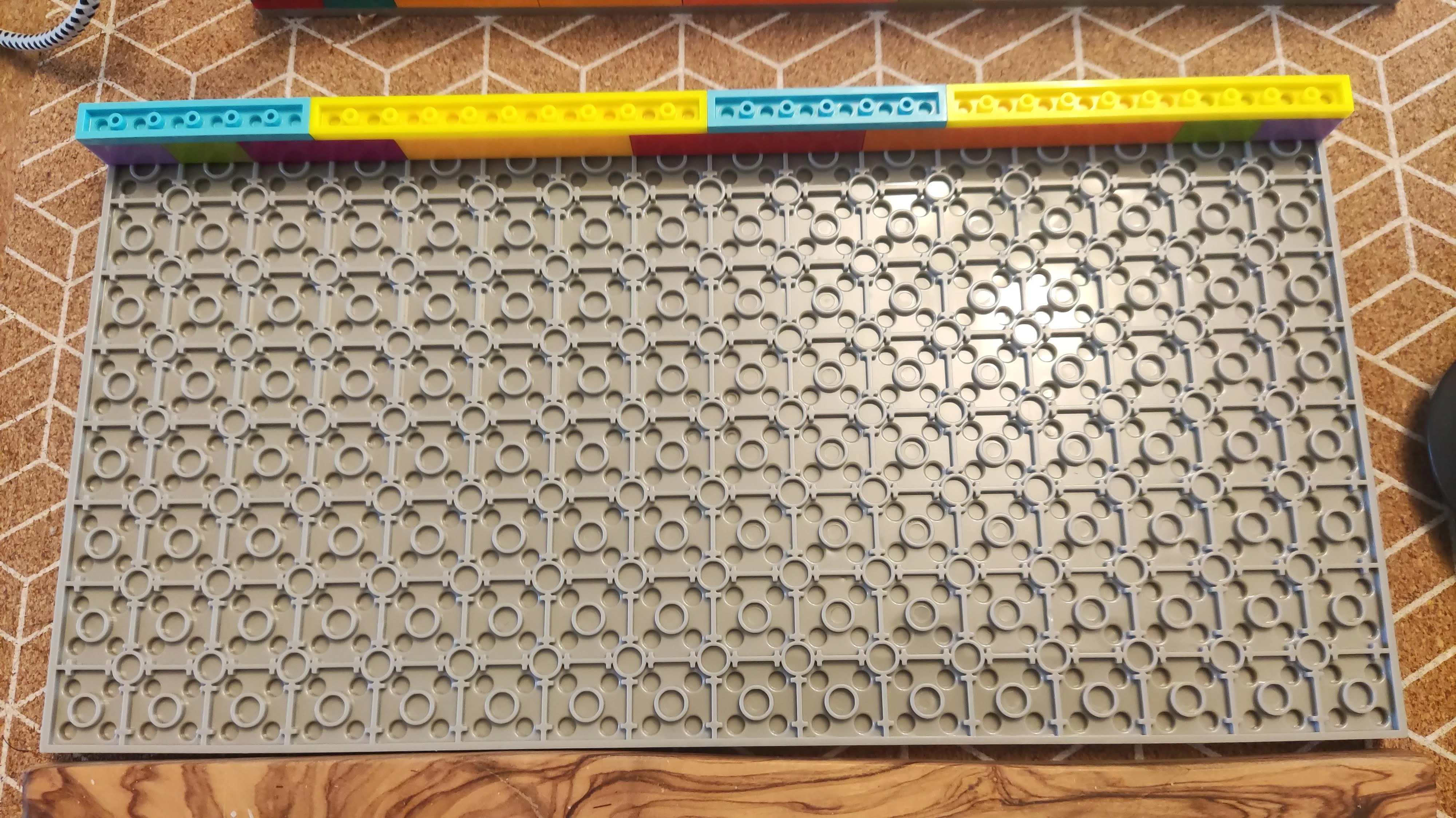
- lego: suggested 1x2 plates(46) or 1x4 plates some colours fit better than others. bricks of same sizes if you want to use battery
- double sided plate 16x32 studs or 2 16x16 (helps with pcb bending).... you will need to live with a compatible since lego does not make them in this size, one thing i noticed is some plates may make the pcb to slightly bend... seems gray coloured ones are ok... no idea why.
- 4 1x1 lego tiles or eyes.(optionally)
- optional 4 2x2 corner plates(optionally)
- 66 signal diodes 1N4148 , do 35 or sod 123
- 5 10KΩ tht or smd 1206 resitors
- 1 5.1KΩ tht or smd 1206 resitors
- xiao rp2040( and soon I hope or nrf52840), see links above.
- 2 shift registers 74HC595, soic16 surface mount
- 1 shift registers 74HC589, soic16 surface mount
- 1 2n7002 FET - sot23 surface mount
- optional, decoupling capacitors 3, 100nf, or sockets with them already installed, or surface mount
- optional but recommended female headers for socketing the mcu.
- pogo pins if you want a battery
- lipo battery if you want to power it by battery.
- socket for battery, 2 pin PH 2.0
- rotary encoder (I got this ec11 Bourns 24 Pulse Incremental Mechanical Rotary Encoder with a 6 mm Flat Shaft but any similar shall do)
- micro switch on/off 1p2t 4mm.
- optional, oled 128x32 i2c (4 pins)
- optional, dil socket 1x4 row for oled.
- optional, eink ssd1680 from weact, 2x4 header and socket
rev 10
revision 10 superseeded by rev11
- lego: suggested 1x2 plates(46) or 1x4 plates some colours fit better than others. bricks of same sizes if you want to use battery
- double sided plate 16x32 studs or 2 16x16 (helps with pcb bending).... you will need to live with a compatible since lego does not make them in this size, one thing i noticed is some plates may make the pcb to slightly bend... seems gray coloured ones are ok... no idea why.
- 4 1x1 lego tiles or eyes.(optionally)
- optional 4 2x2 corner plates(optionally)
- 66 signal diodes 1N4148 , do 35 or sod 123
- 5 10KΩ tht or smd 1206 resitors
- 1 5.1KΩ tht or smd 1206 resitors
- xiao rp2040( and soon I hope or nrf52840), see links above.
- 2 shift registers 74HC595, soic16 surface mount
- 1 shift registers 74HC589, soic16 surface mount
- 1 2n7002 FET - sot23 surface mount
- optional, decoupling capacitors 3, 100nf, or sockets with them already installed, or surface mount
- optional but recommended female headers for socketing the mcu.
- pogo pins if you want a battery
- lipo battery if you want to power it by battery.
- socket for battery, 2 pin PH 2.0
- rotary encoder (I got this ec11 Bourns 24 Pulse Incremental Mechanical Rotary Encoder with a 6 mm Flat Shaft but any similar shall do)
- micro switch on/off 1p2t 4mm.
- oled 128x32 i2c (4 pins)
- dil socket 1x4 row for oled.
rev 9
revision 9
- lego: suggested 1x2 plates(46) or 1x4 plates some colours fit better than others. bricks of same sizes if you want to use battery
- double sided plate 16x32 studs or 2 16x16 (helps with pcb bending).... you will need to live with a compatible since lego does not make them in this size, one thing i noticed is some plates may make the pcb to slightly bend... seems gray coloured ones are ok... no idea why.
- 4 1x1 lego tiles or eyes.(optionally)
- optional 4 2x2 corner plates(optionally)
- 66 signal diodes 1N4148 , do 35 or sod 123
- 5 10KΩ tht resitors
- xiao rp2040( and soon I hope or nrf52840), see links above.
- 2 shift registers 74HC595, tht style and dip 16 sockets
- 1 shift registers 74HC165, tht style and dip 16 socket
- optional, decoupling capacitors 3, 100nf, or sockets with them already installed
- optional but recommended female headers for socketing the mcu.
- pogo pins if you want a battery
- lipo battery if you want to power it by battery.
- socket for battery, 2 pin PH 2.0
- rotary encoder (I got this ec11 Bourns 24 Pulse Incremental Mechanical Rotary Encoder with a 6 mm Flat Shaft but any similar shall do)
- micro switch on/off 1p2t 4mm.
rev 7/8
revision 7/8
- lego: suggested 1x2 plates(46) or 1x4 plates some colours fit better than others. bricks of same sizes if you want to use battery
- double sided plate 16x32 studs or 2 16x16 (helps with pcb bending).... you will need to live with a compatible since lego does not make them in this size, one thing i noticed is some plates may make the pcb to slightly bend... seems gray coloured ones are ok... no idea why.
- 4 1x1 lego tiles or eyes.(optionally)
- optional 4 2x2 corner plates(optionally)
- 65 signal diodes 1N4148 , do 35 or sod 123
- xiao rp2040 or nrf52840, see links before.
- 2 shift registers 74HC595, tht style and dip 16 sockets
- optional, decoupling capacitors 2, 100nf
- optional but recommended female headers for socketing the mcu.
- pogo pins if you want a battery
- lipo battery if you want to power it by battery.
- rotary encoder (I got this ec11 Bourns 24 Pulse Incremental Mechanical Rotary Encoder with a 6 mm Flat Shaft but any similar shall do)
rev5/6
revision 5/6
- lego: suggested 1x2 plates(46) or 1x4 plates some colours fit better than others.
- double sided plate 16x32 studs.... you will need to live with a compatible since lego does not make them in this size, one thing i noticed is some plates may make the pcb to slightly bend... seems gray coloured ones are ok... no idea why.
- 4 1x1 lego tiles or eyes.(optionally)
-
optional 4 2x2 corner plates(optionally)
-
65 signal diodes 1N4148 , do 35 or sod 123
- 2 resistors (510Ω (R1,R2) works fine for green and yellow leds you need to check the resistance for the right intensity you want) and 2 leds, resistors need to be computed to match the colour of the led 1kΩ for whites will be bright
- or rp2040 aka Raspberry pico, weact version, teenstar or...
- switches (5 pin) and keycaps... for pcb mount
- rotary encoder (I got this ec11 Bourns 24 Pulse Incremental Mechanical Rotary Encoder with a 6 mm Flat Shaft but any similar shall do)
- jst horizontal header 3 pin, if you add leds strip
- oled 128x32 i2c (4 pins)
- dil socket 1x4 row for oled.
- round pin headers 2x20 for MCU
- 2x20 dil sockets
- usb cable, c or mini depending on the mcu.
rev4
revision 4
- lego: suggested 1x2 plates(46) or 1x4 plates some colours fit better than others.
- double sided plate 16x32 studs.... you will need to live with a compatible since lego does not make them in this size, one thing i noticed is some plates may make the pcb to slightly bend... seems gray coloured ones are ok... no idea why.
- 4 1x1 lego tiles or eyes.(optionally)
-
optional 4 2x2 corner plates(optionally)
-
65 signal diodes 1N4148 , do 35 or sod 123
- 2 resistors (510Ω (R1,R2) works fine for green and yellow leds you need to check the resistance for the right intensity you want) and 2 leds, resistors need to be computed to match the colour of the led 1kΩ for whites will be bright
- or stm32f401 from we act
- or stm32f411 from we act, ask for the firmware
- 100kΩ resistor for (R3)
- switches (5 pin) and keycaps... for pcb mount
- rotary encoder (I got this Bourns 24 Pulse Incremental Mechanical Rotary Encoder with a 6 mm Flat Shaft but any similar shall do)
- jst horizontal header 3 pin, if you add leds strip
- oled 128x32 i2c (4 pins)
- dil socket 1x4 row for oled.
- round pin headers 2x20 for MCU
- dil socket for MCU 40 way 15.24mm or 2x20 dil sockets
- usb cable, c or mini depending on the mcu.
for other revisions not listed same as rev4 but replace the mcu with the right one
case
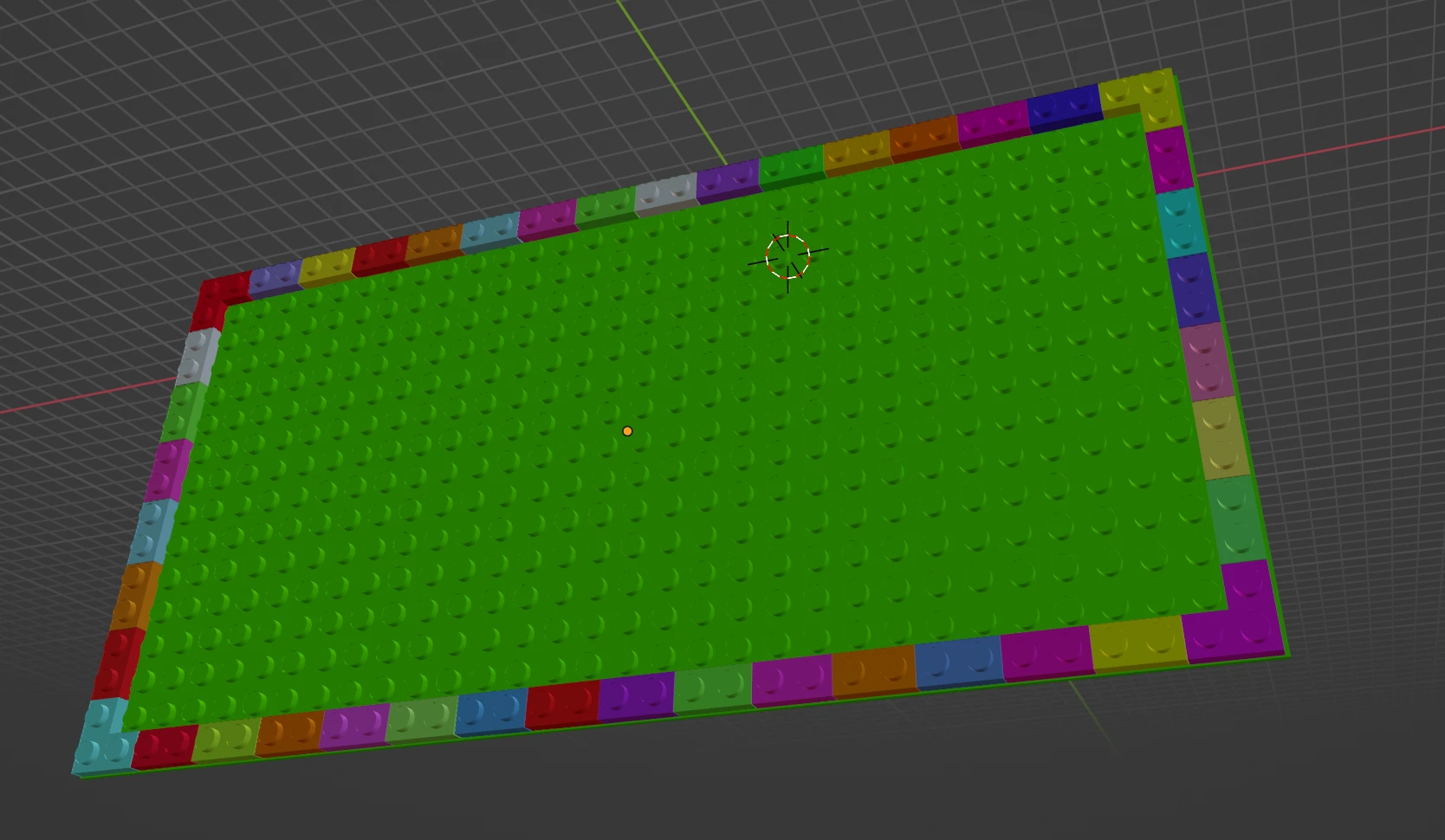
3d render
parts for case
case front
case back
case side
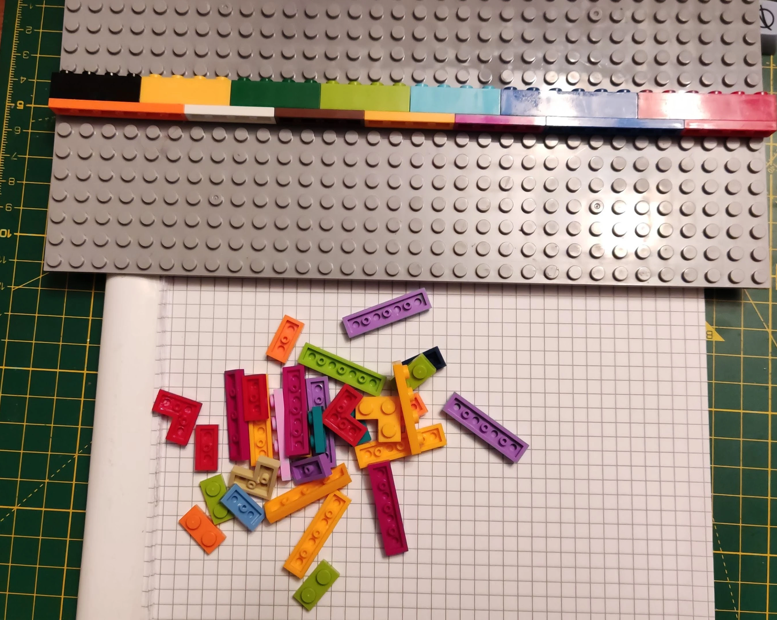
assembly
this is a very rushed assembly guide but shall give you the main idea.
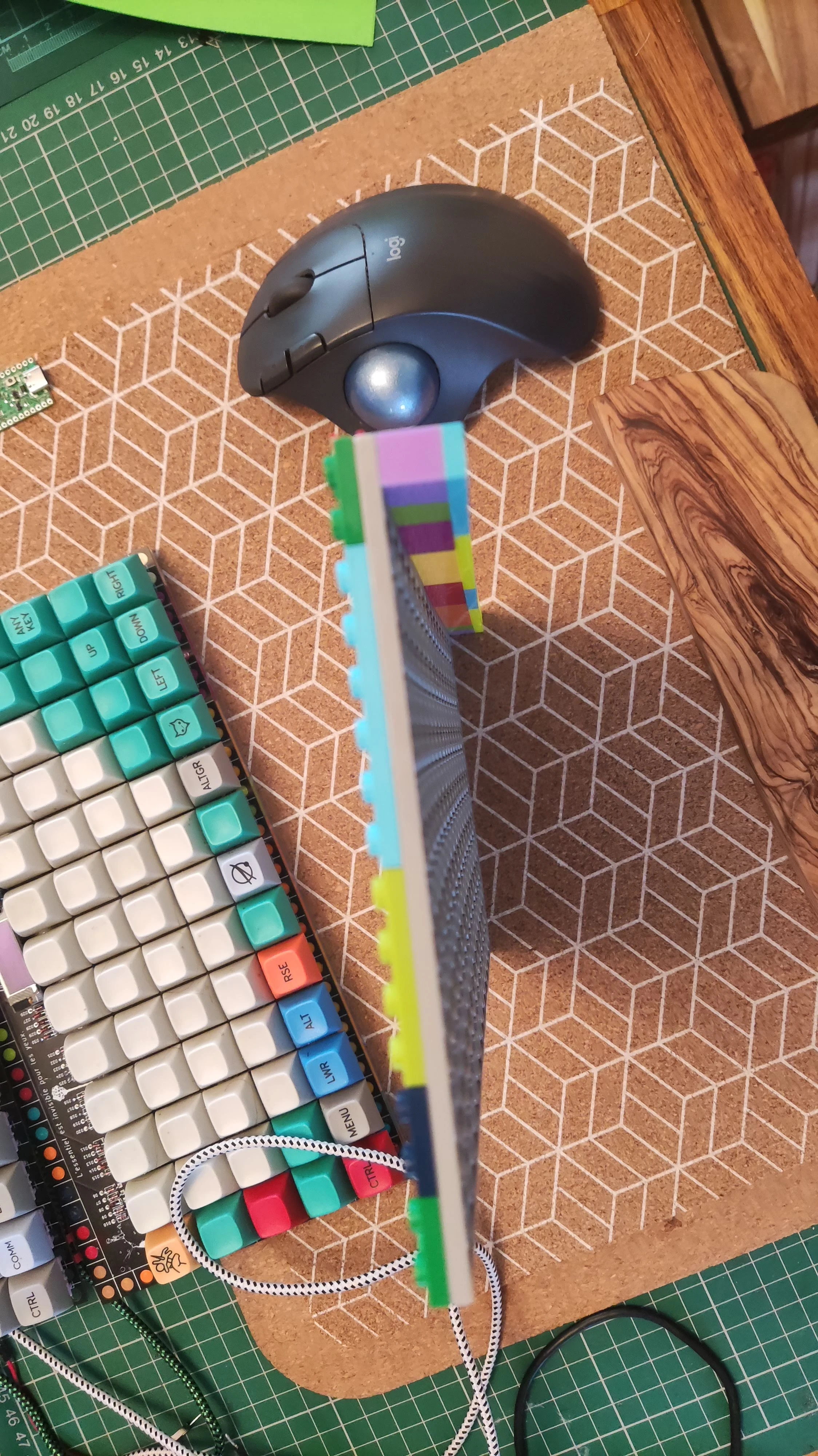
thickness
depending on what you want the box can come out very thin.. 1 base plate(single or double, flat or angled usage) plus pcb(1.6mm) plus one plate intermediate(3.2mm). that is thin. This shall allow you to put in a sheet of foam for sound dampening.
2 layers of intermediate plates, for thicker foam sheet or for led strip which is connected by hand to the pins or holes... no jst header.
1 full brick if you want a jst header.
3d render
rev11
rev10
rev9
the 3d render rev9
rev7-8
the 3d render rev7/rev8

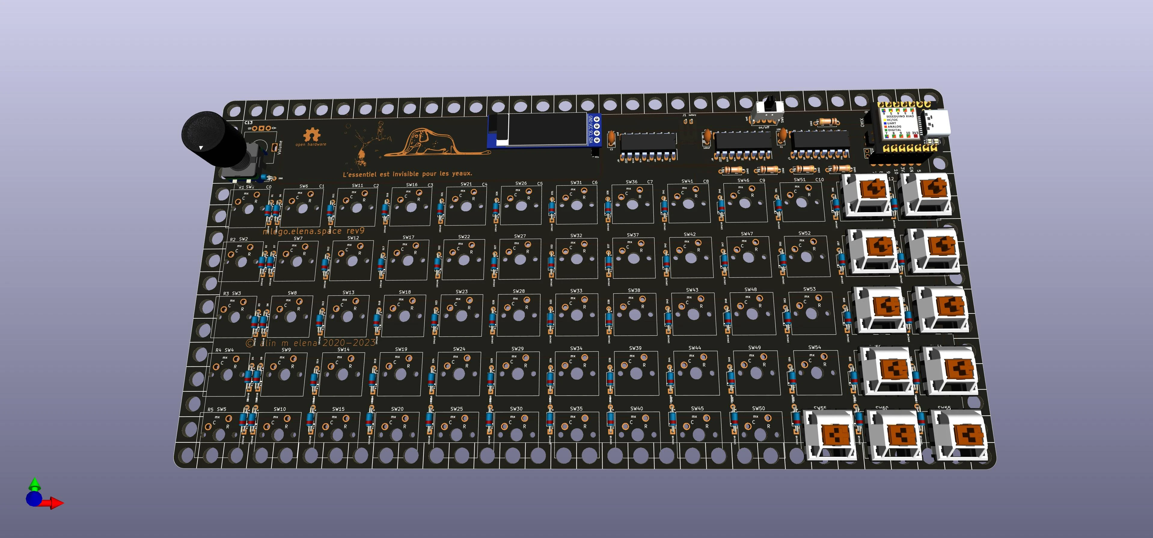
rev5/6
the 3d render rev5/rev6
rev4
the 3d rev4
rev2
version 2
rev1
the 3d render looks like (version 1)
schematic
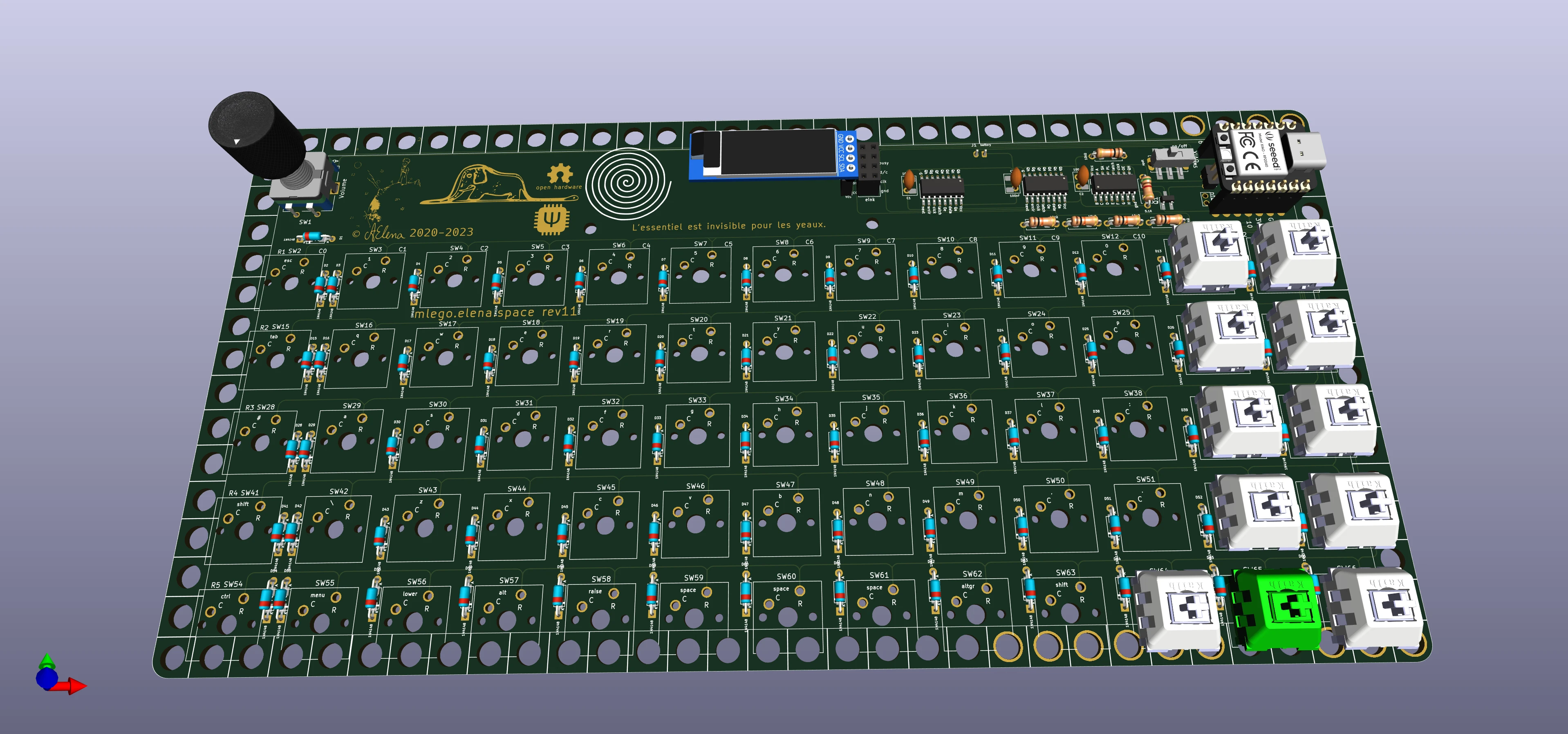
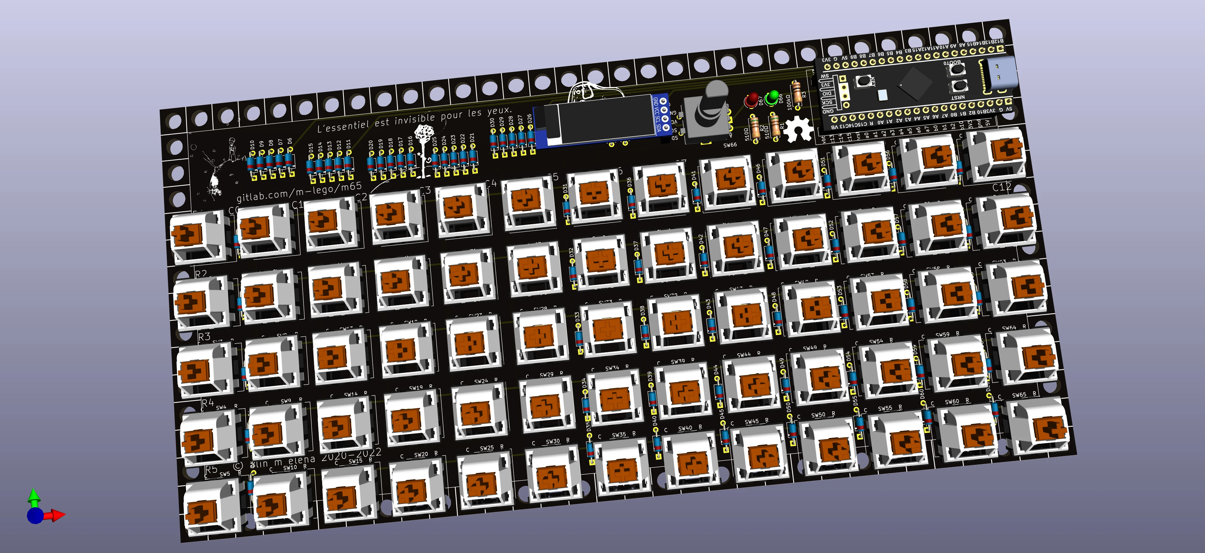
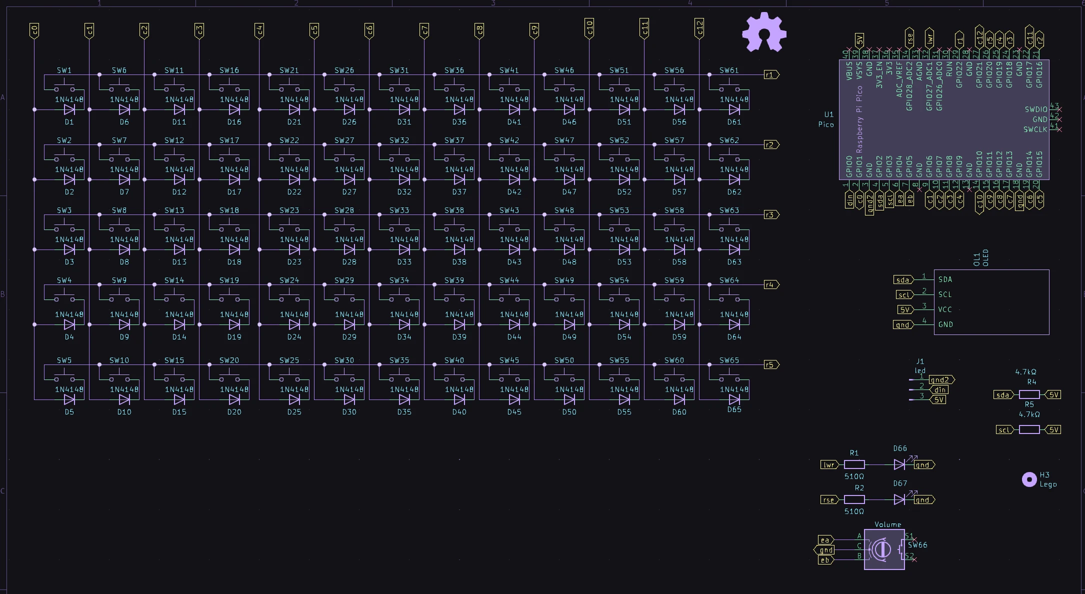
rev11
rev10

rev9
rev7
rev5
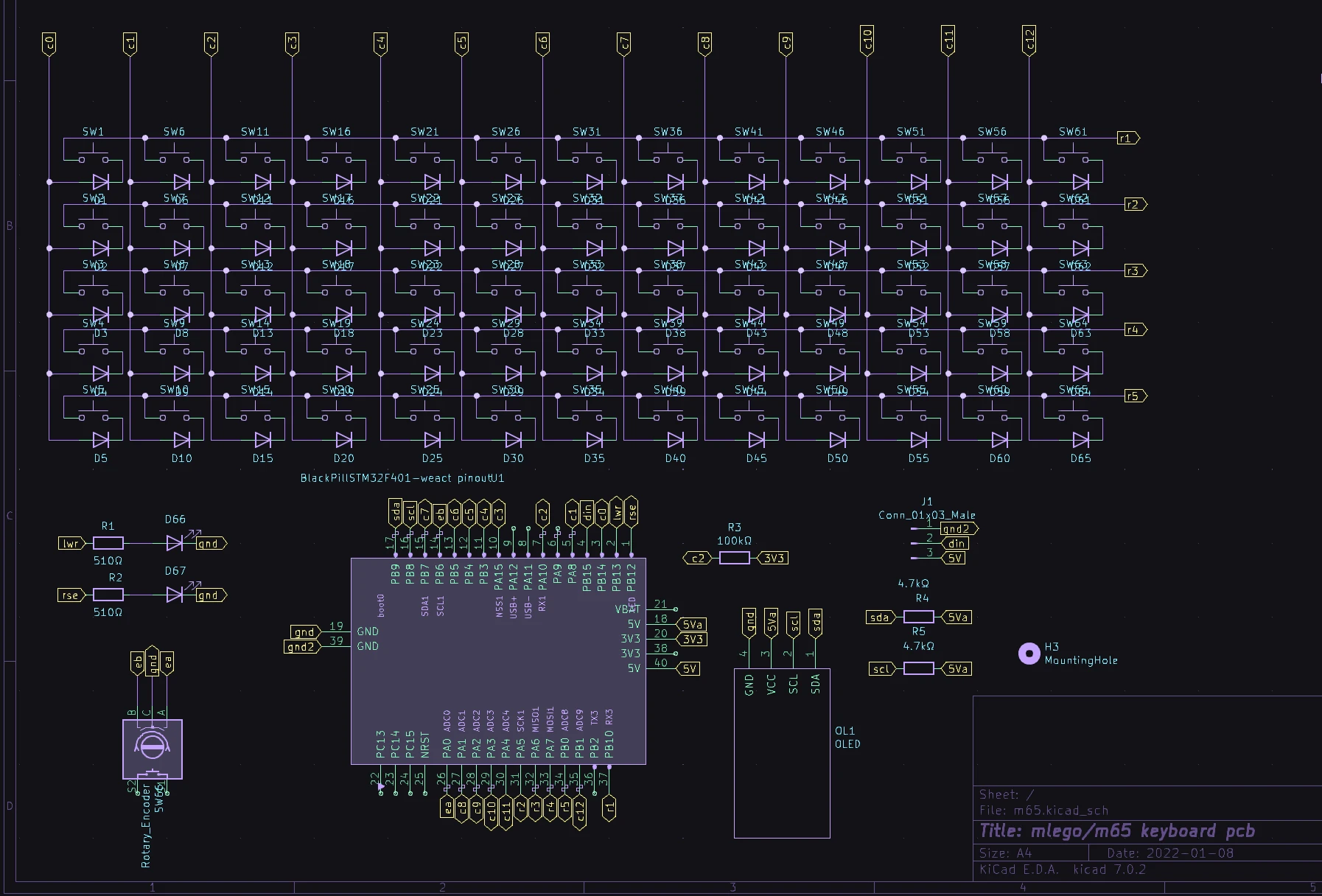
rev4
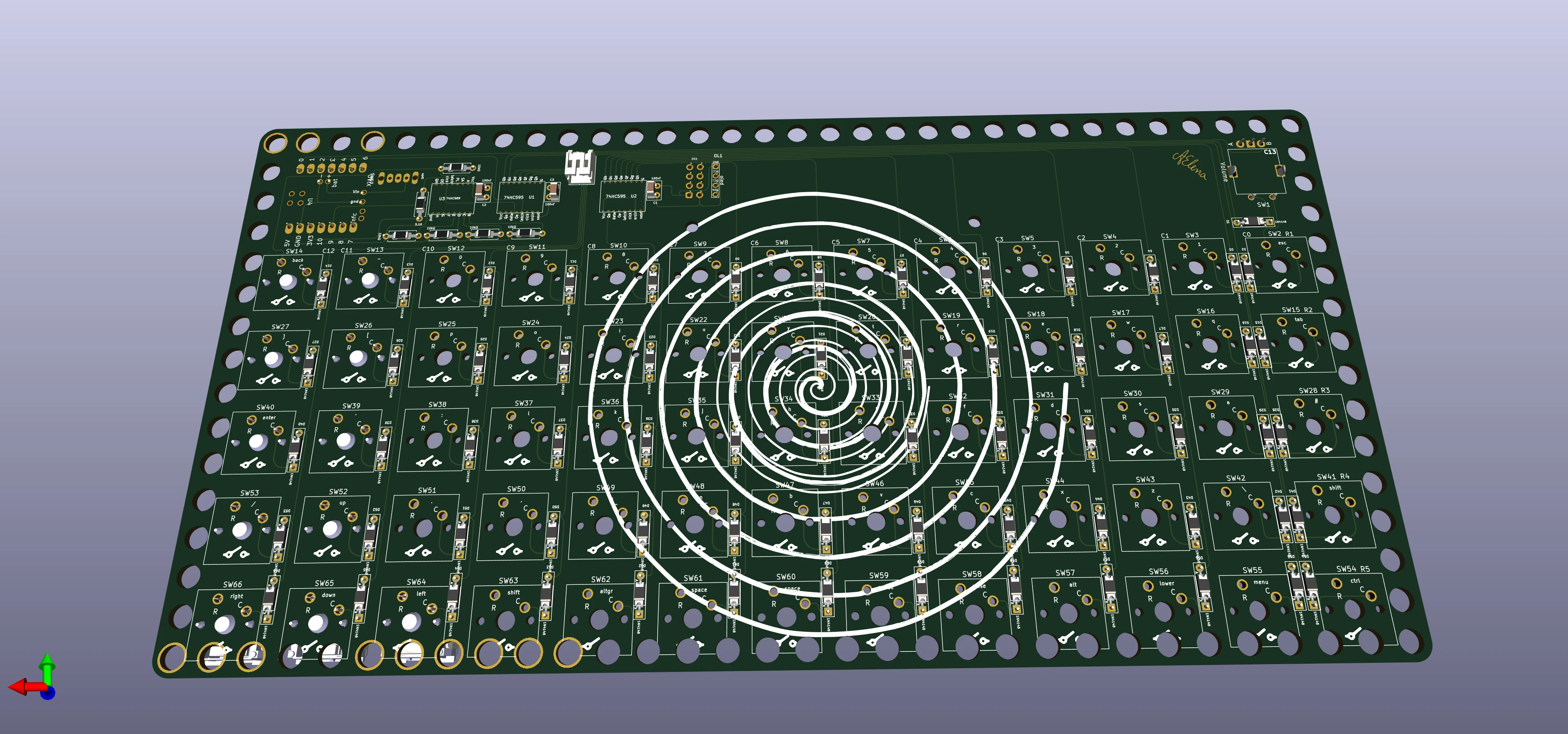
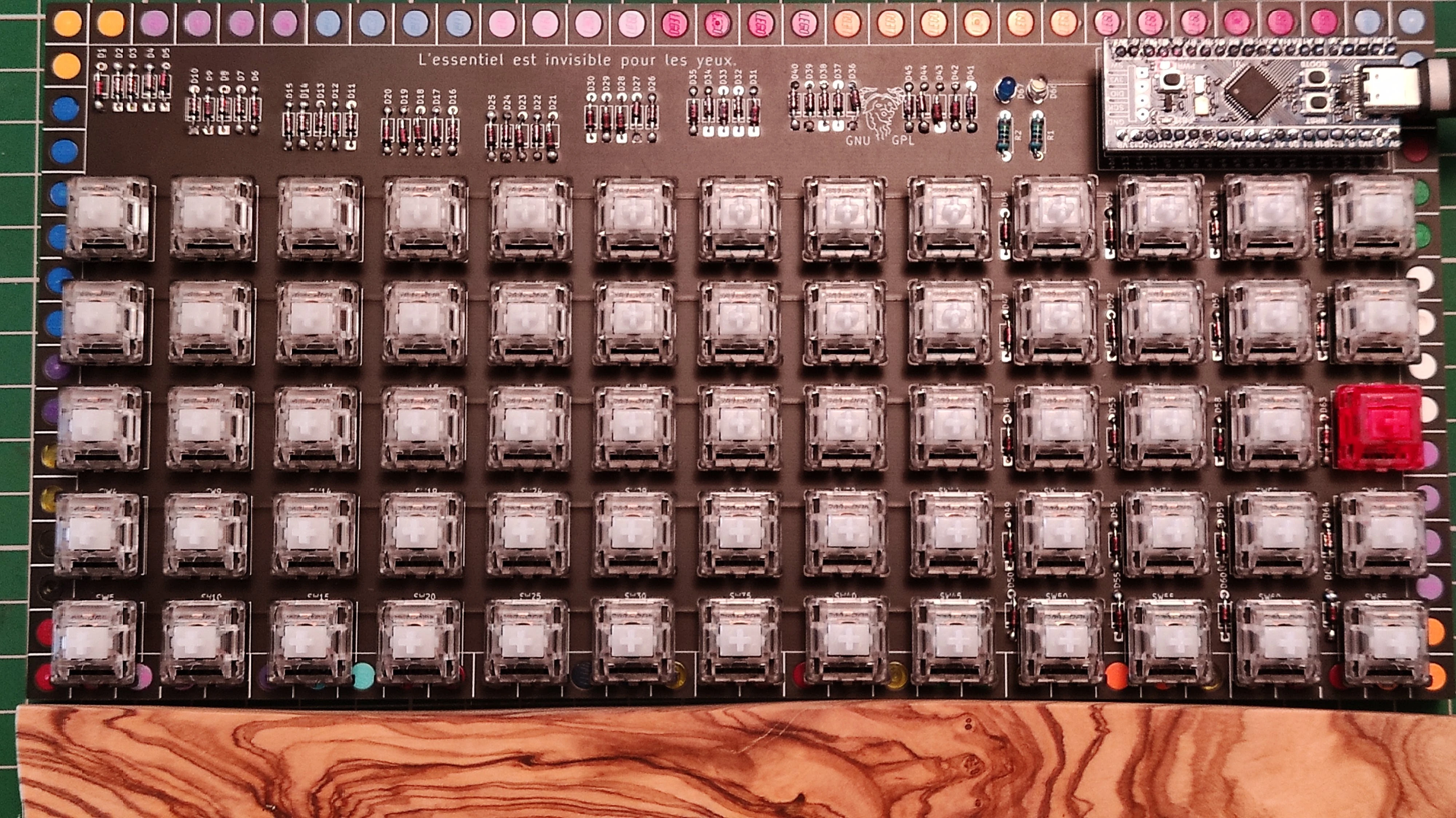
pcb
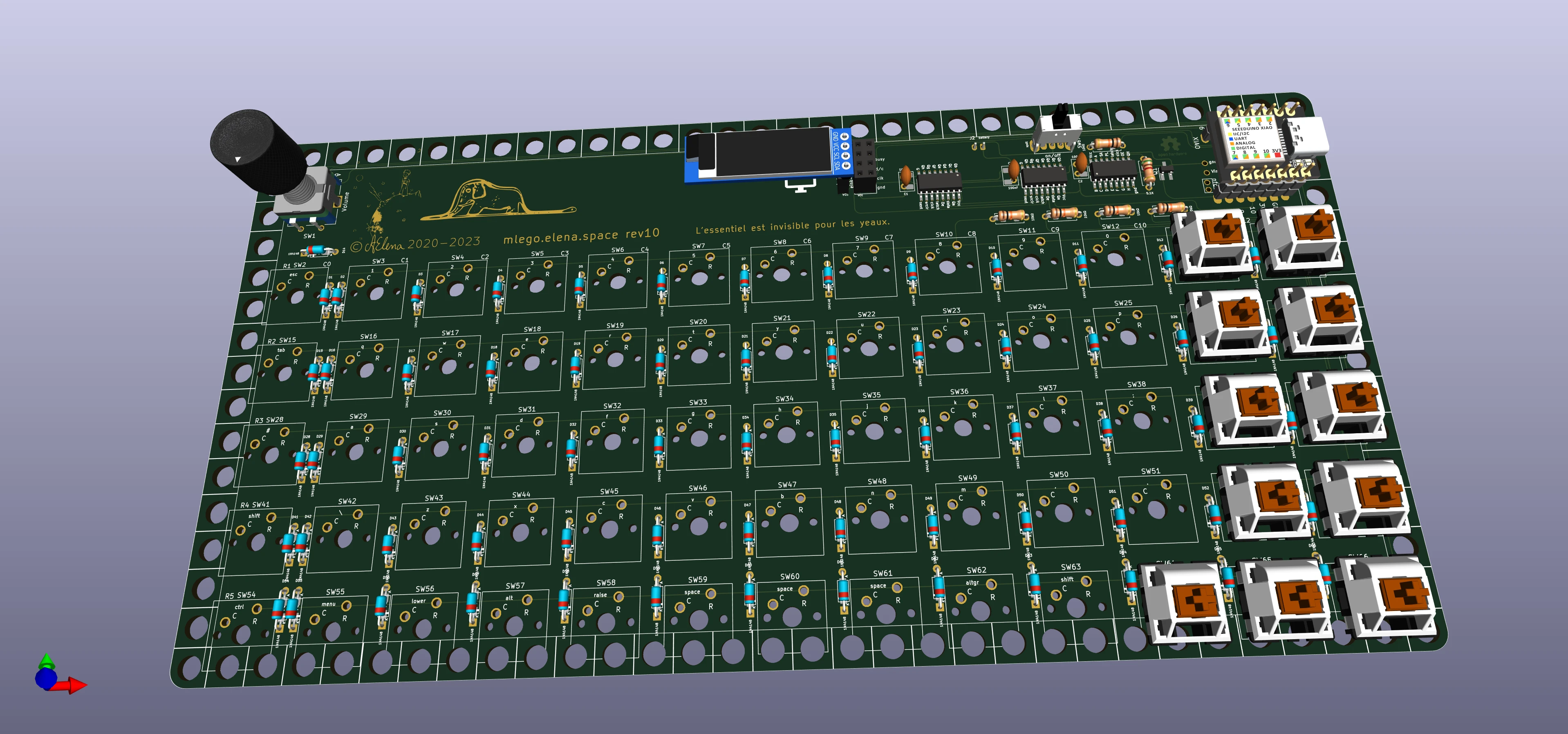
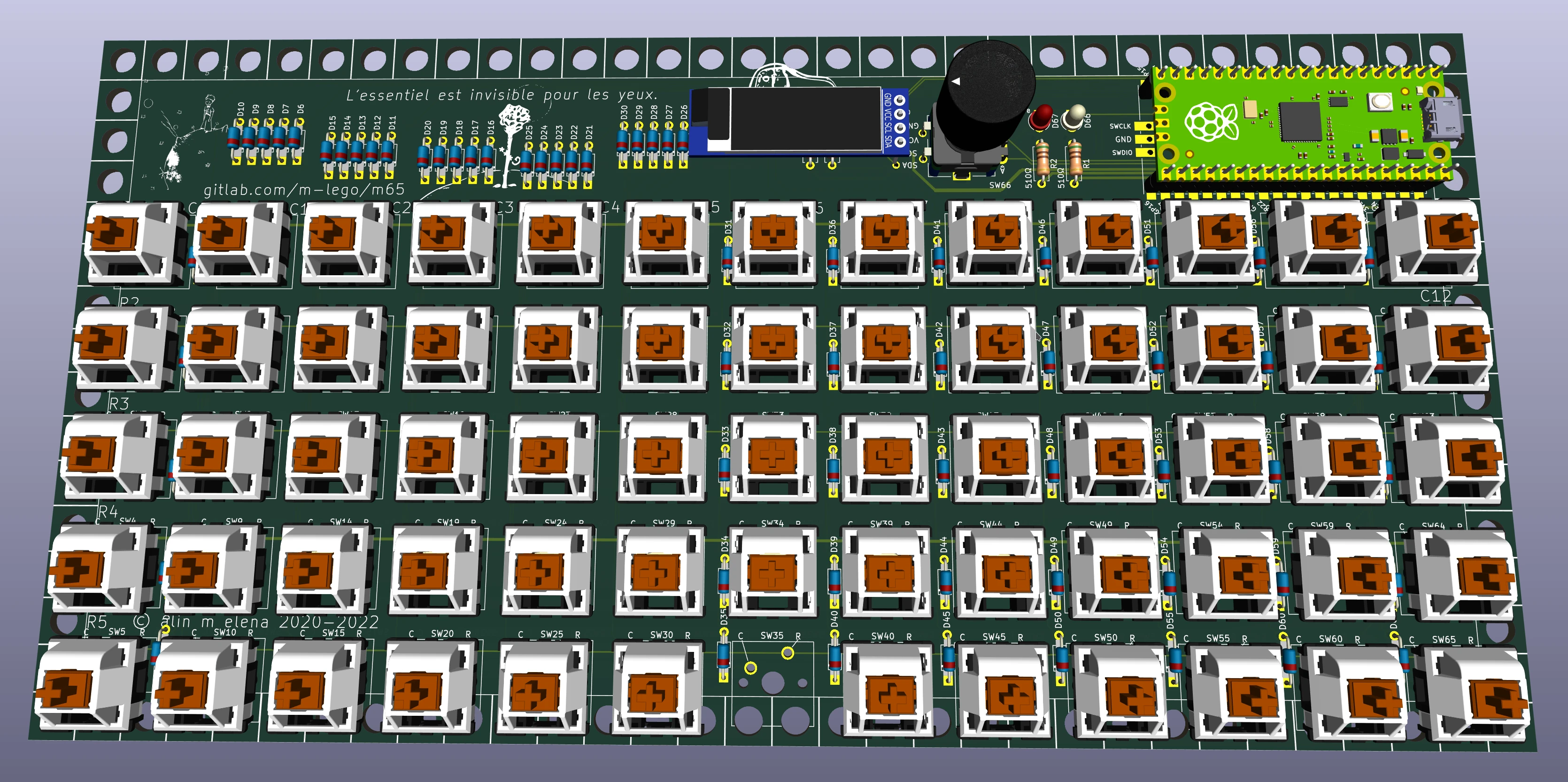
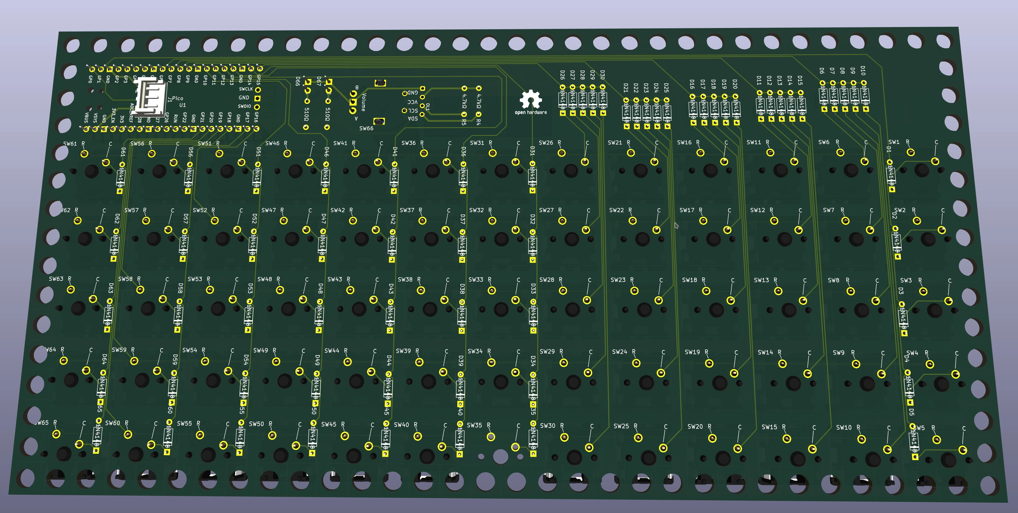
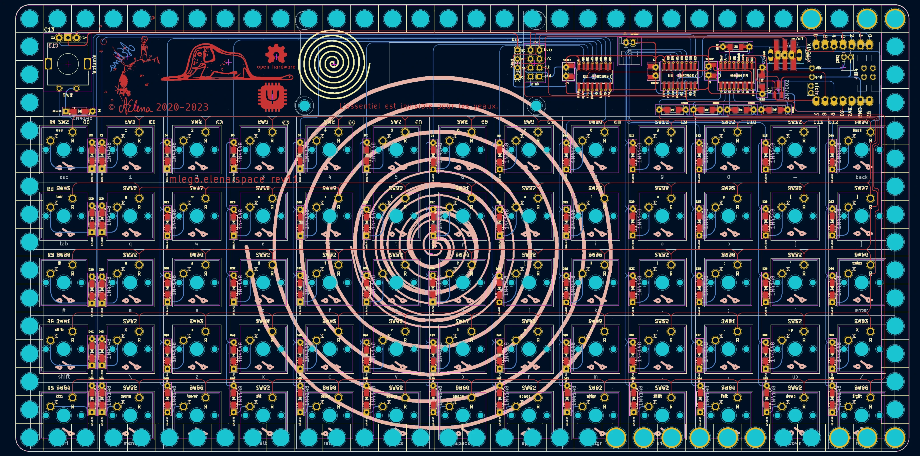
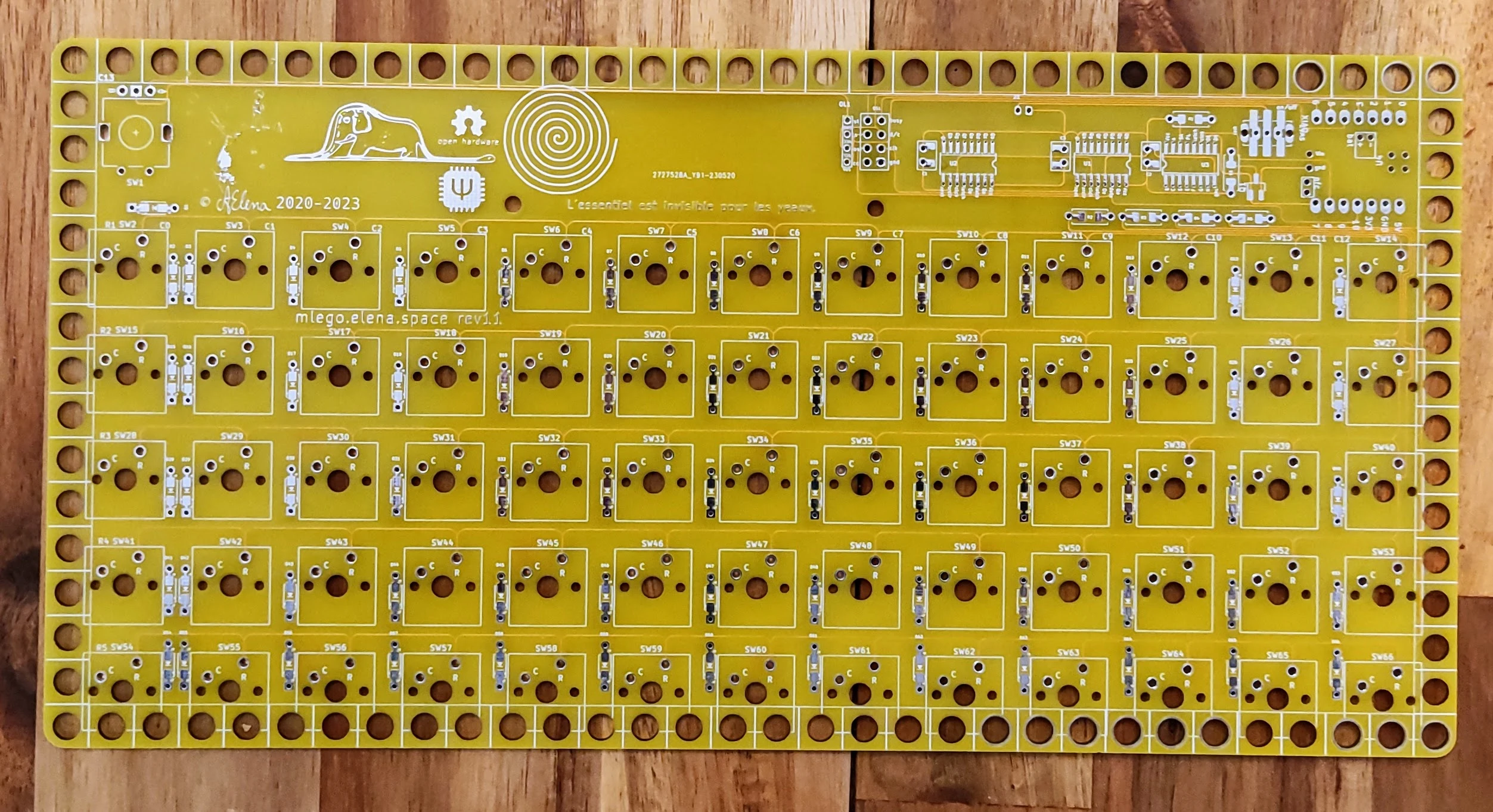
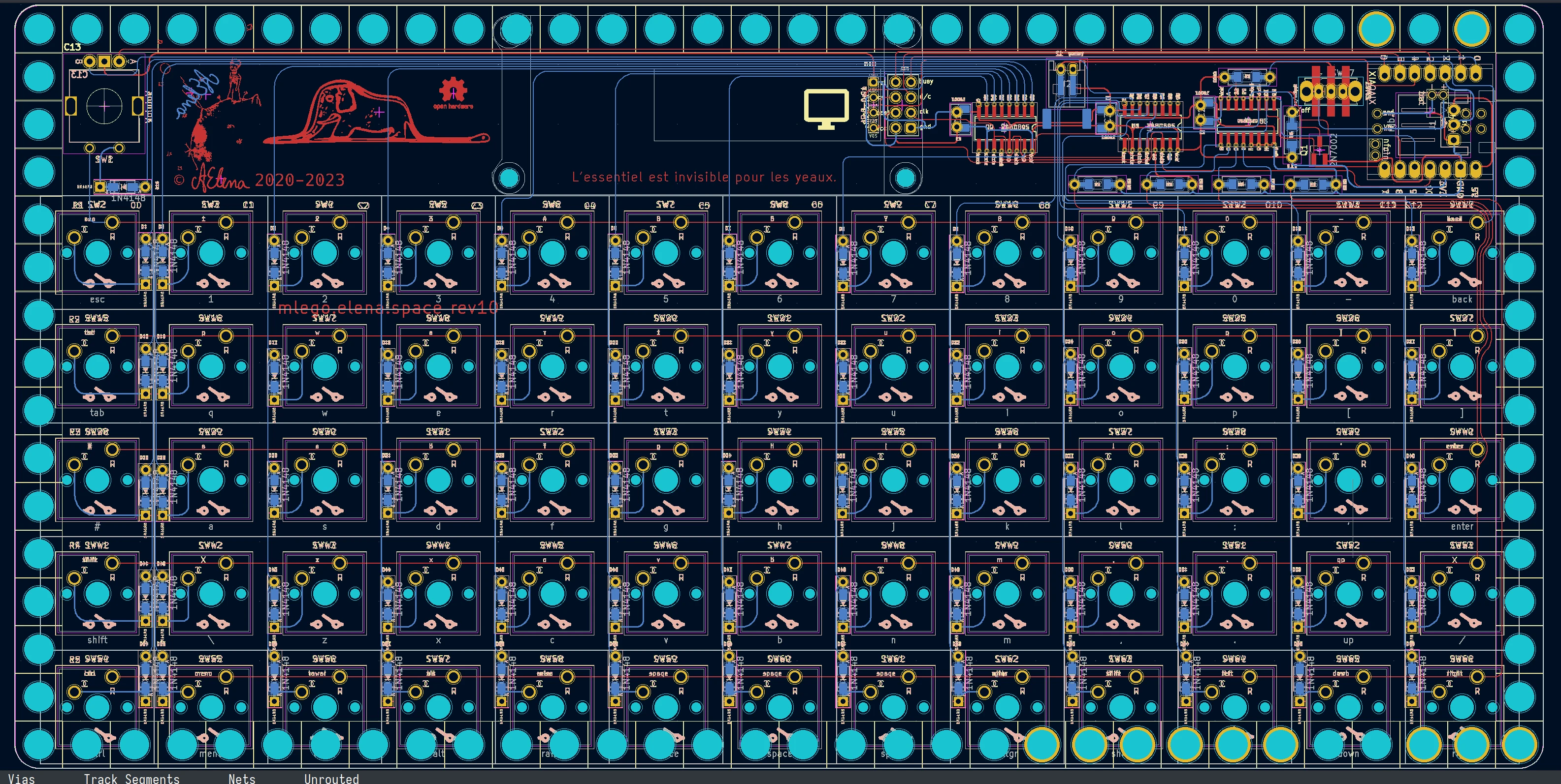
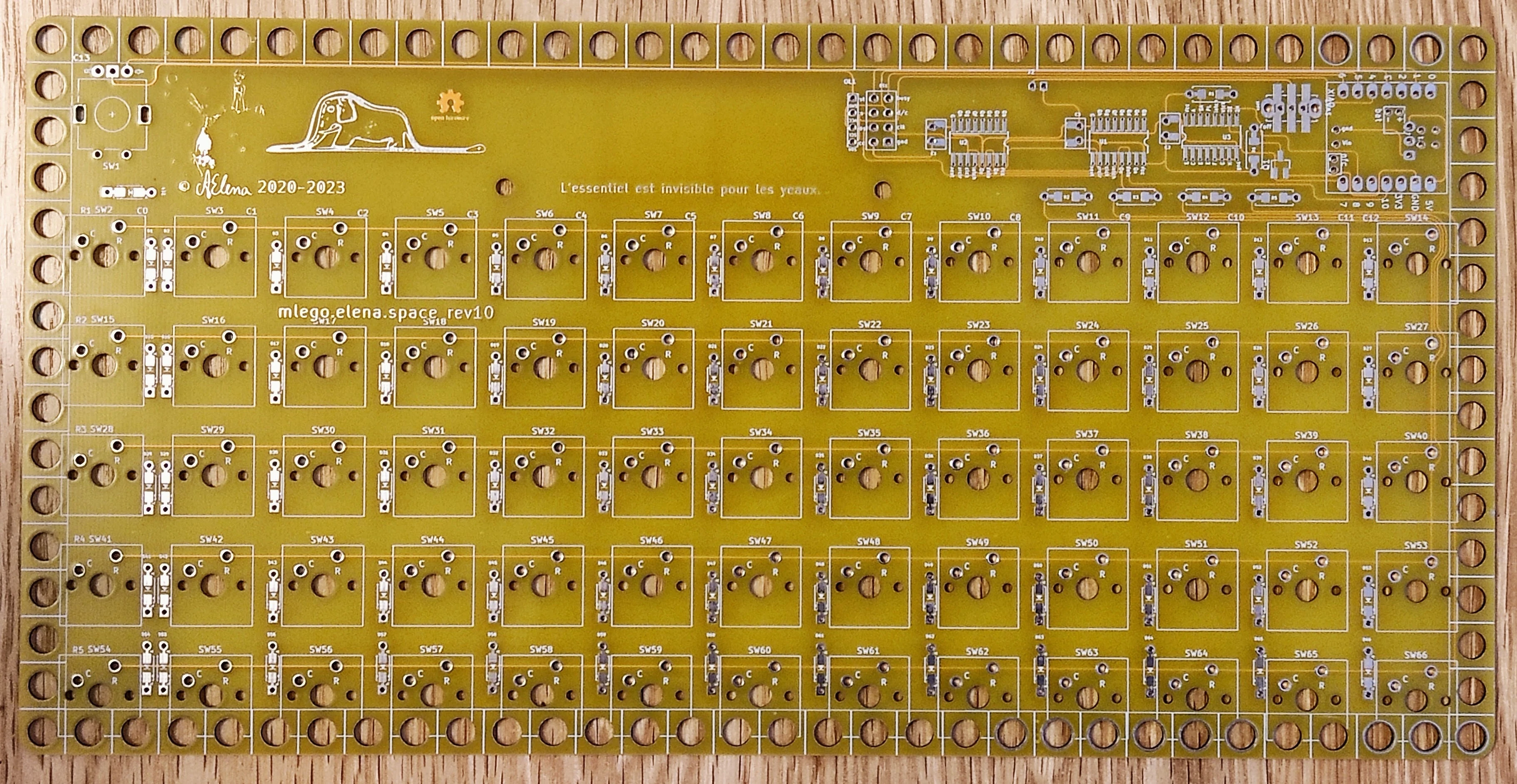
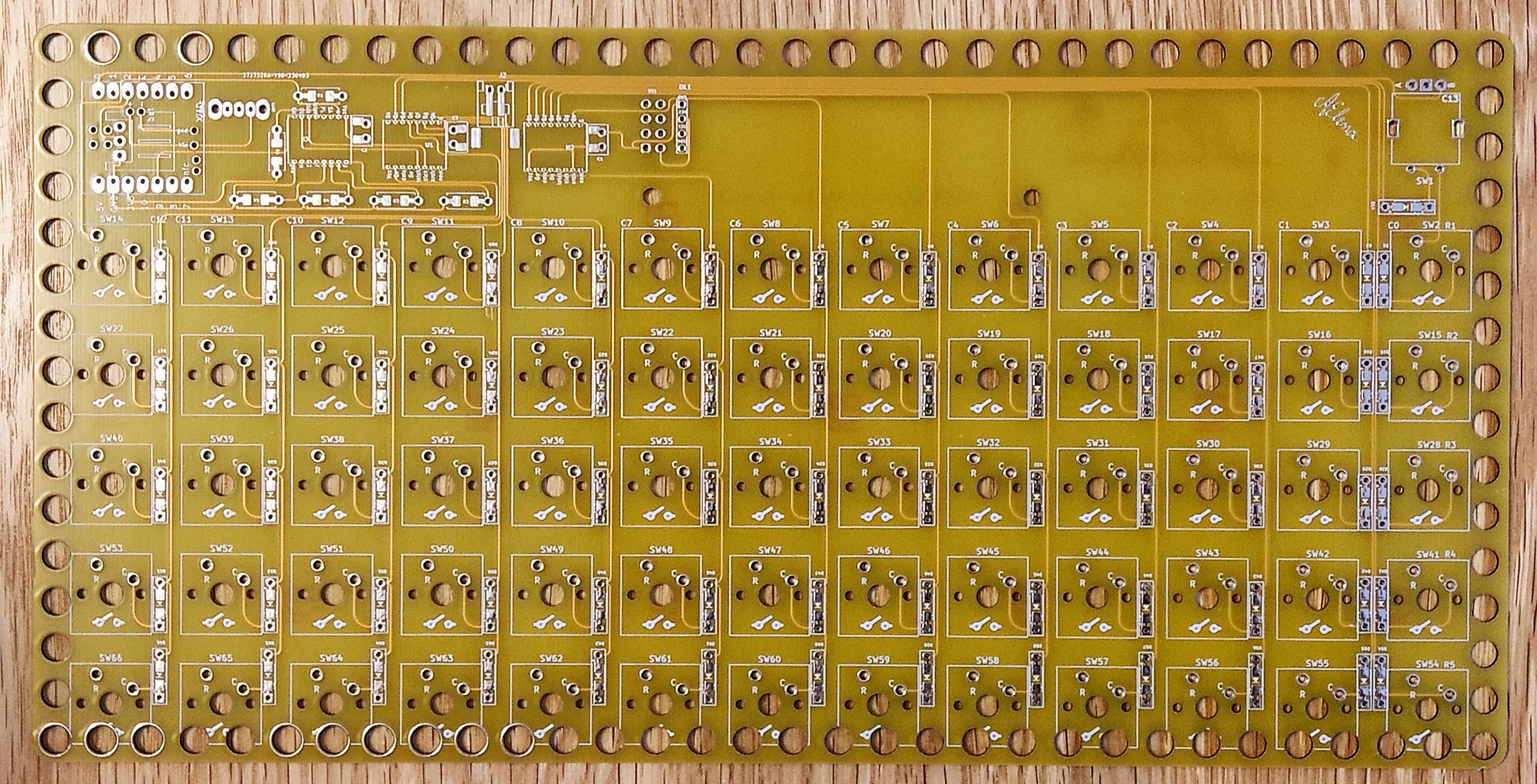
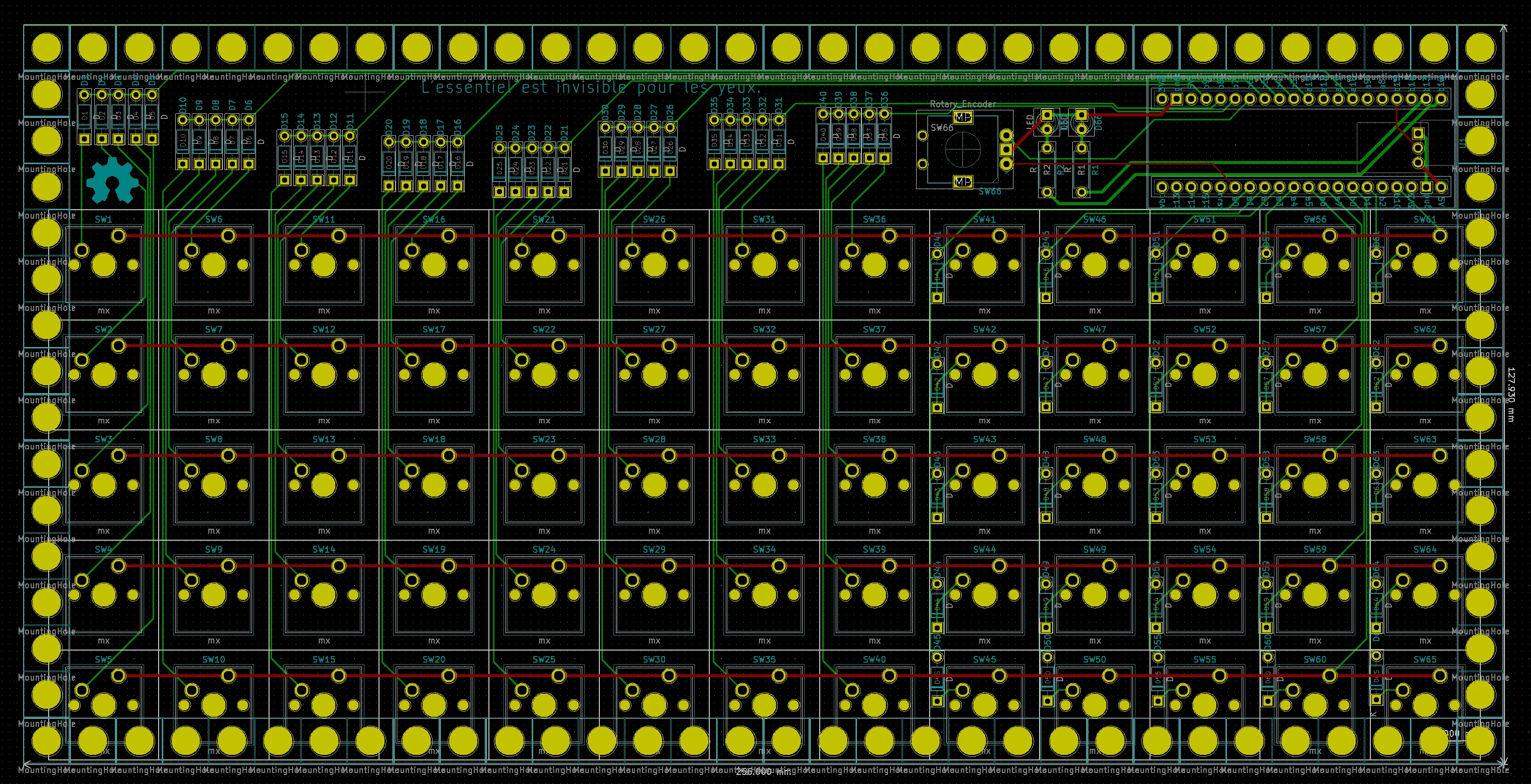
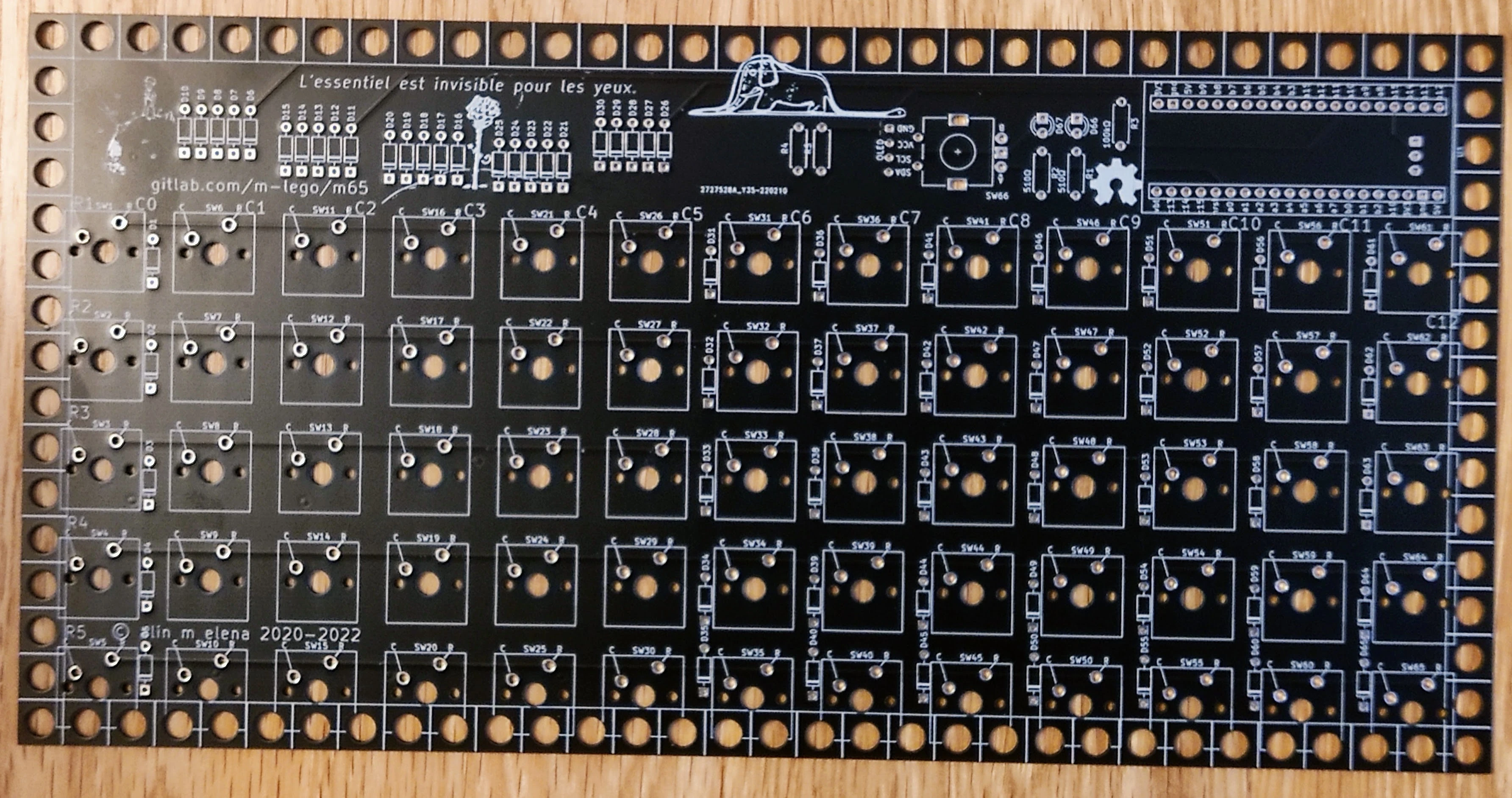
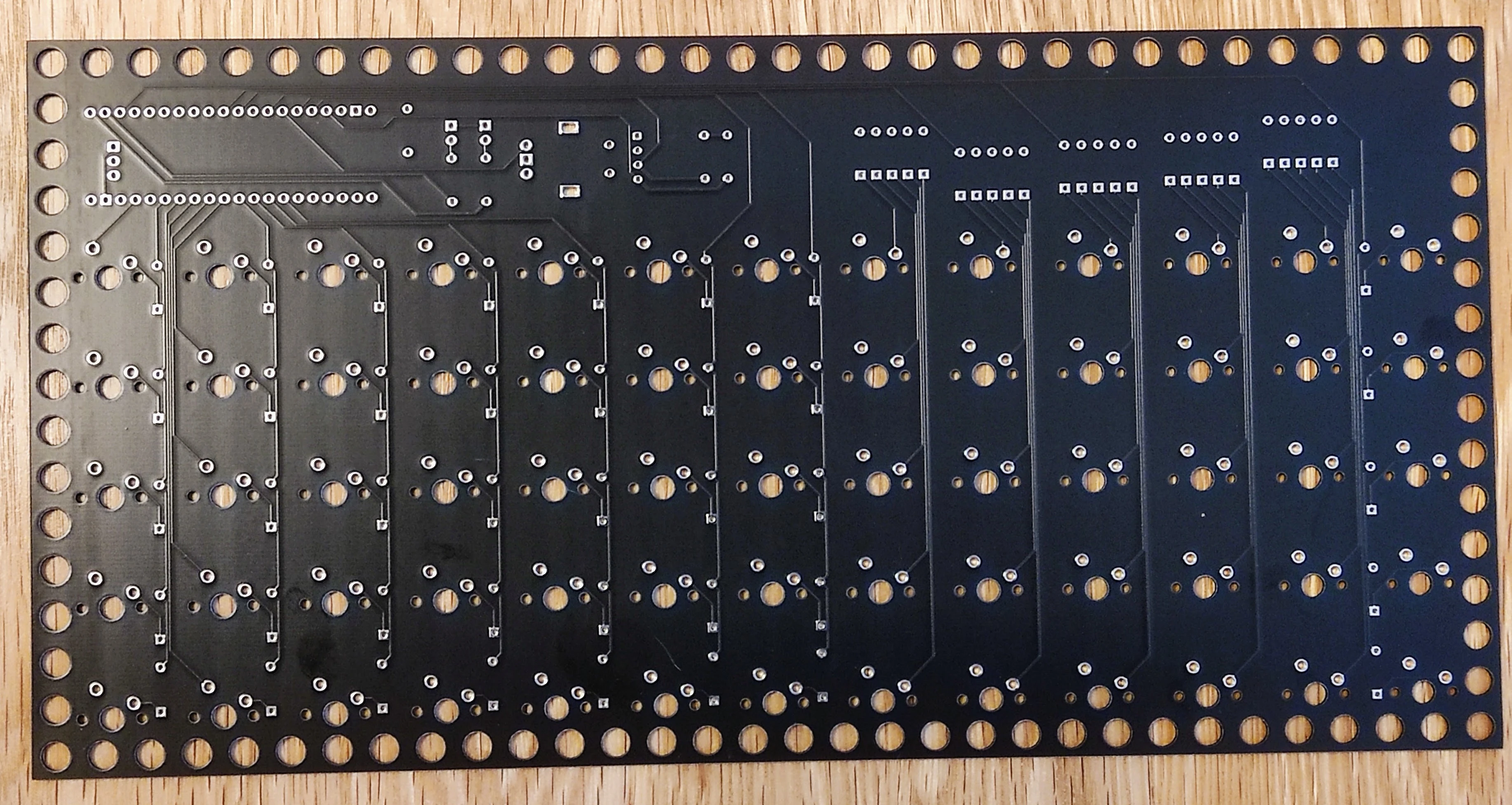
rev11
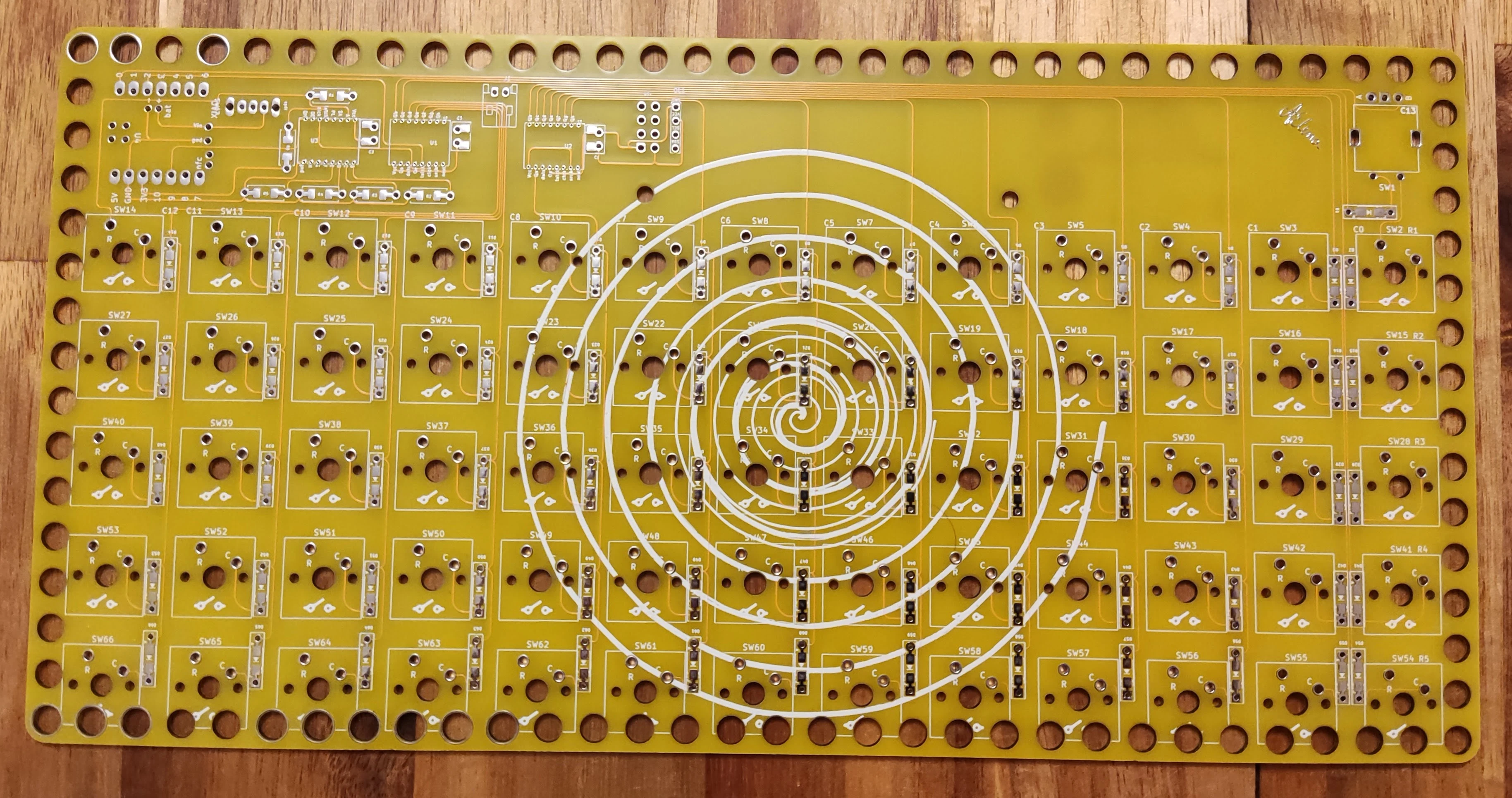
rev10
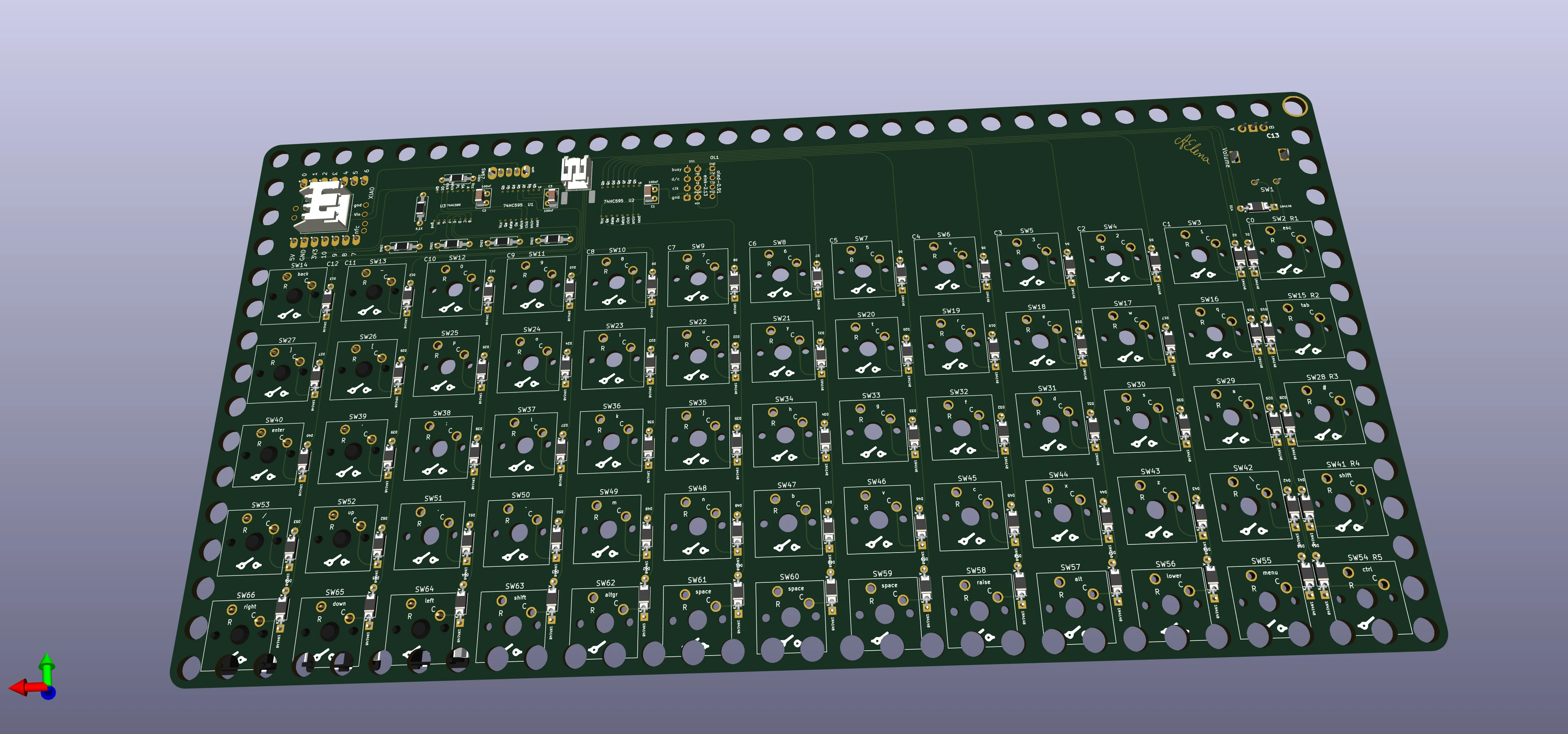
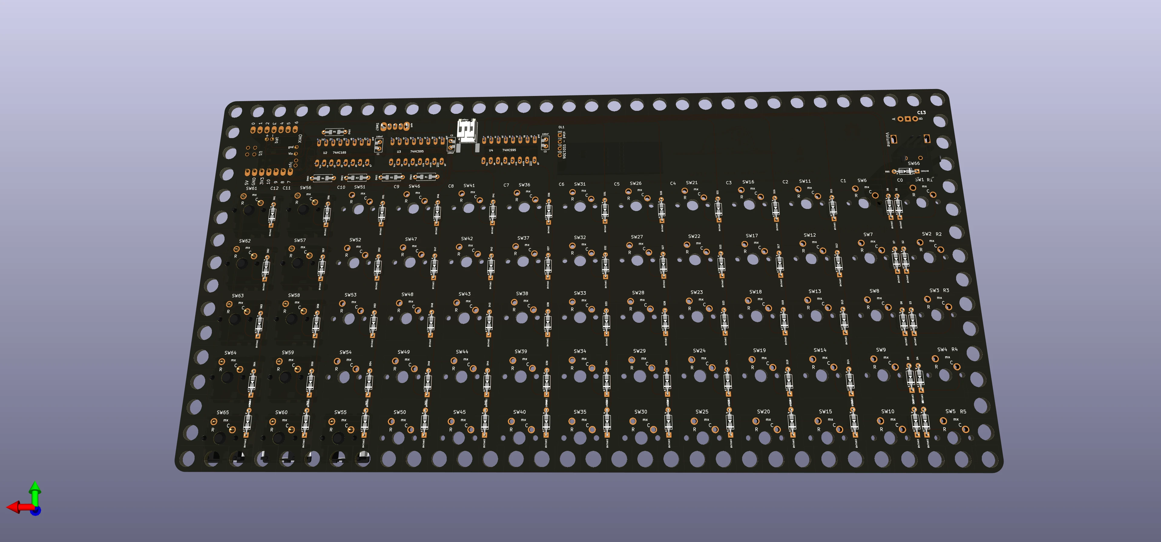
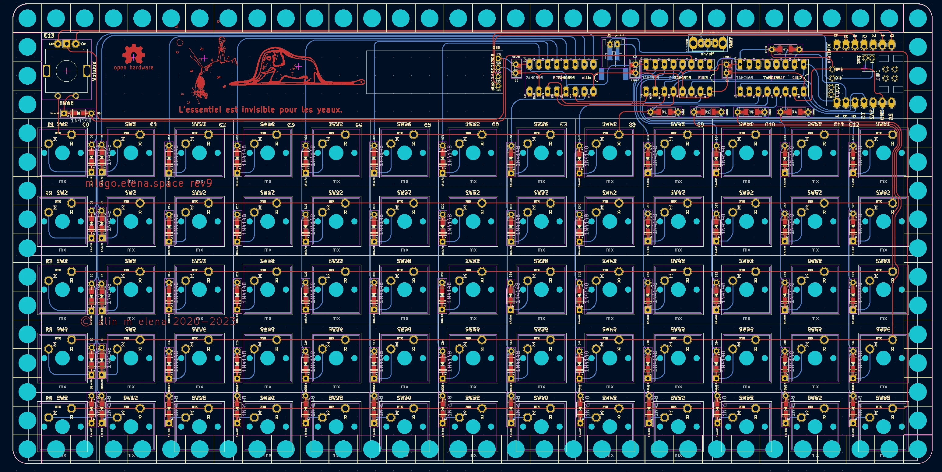
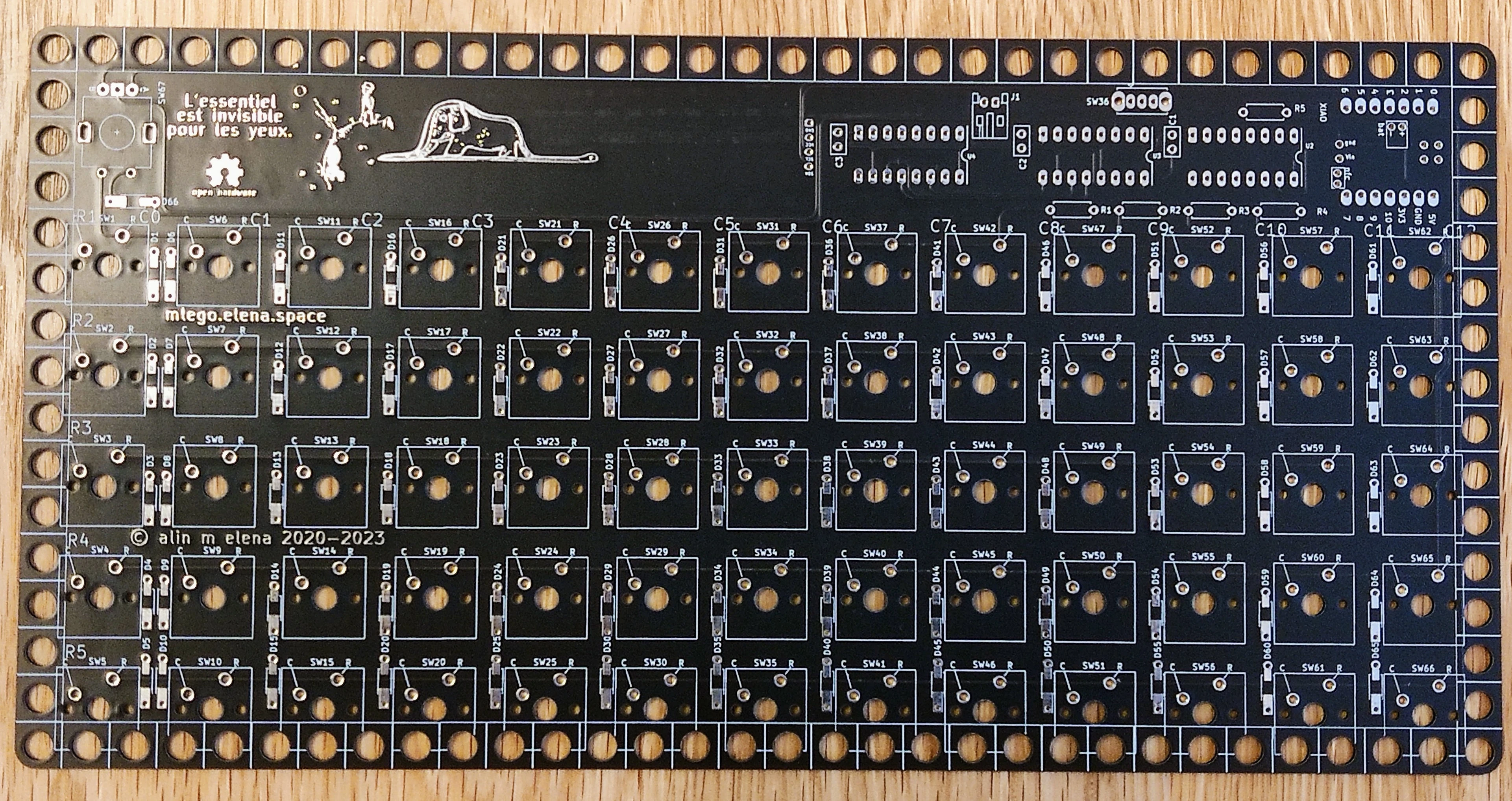
rev9
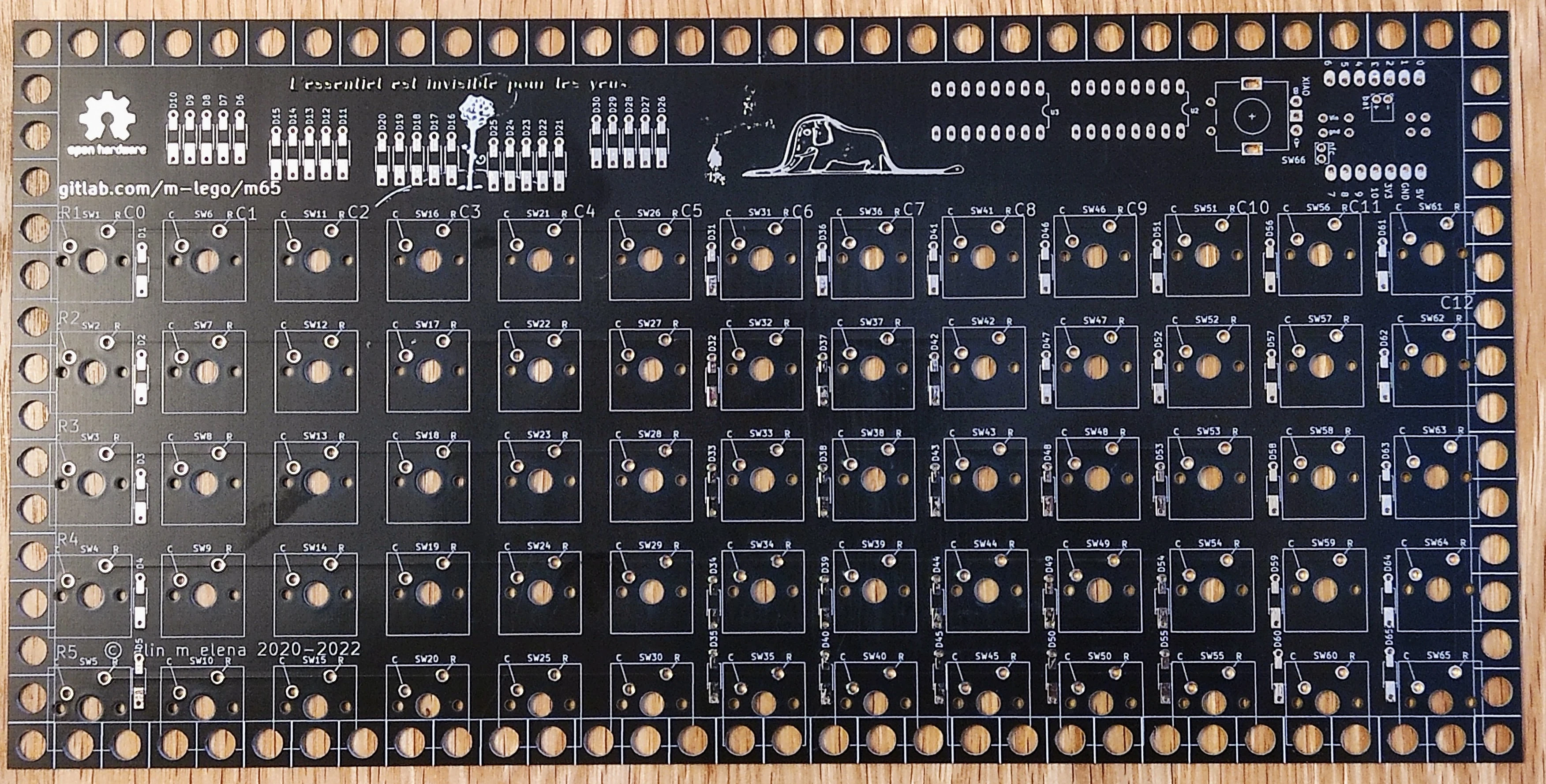
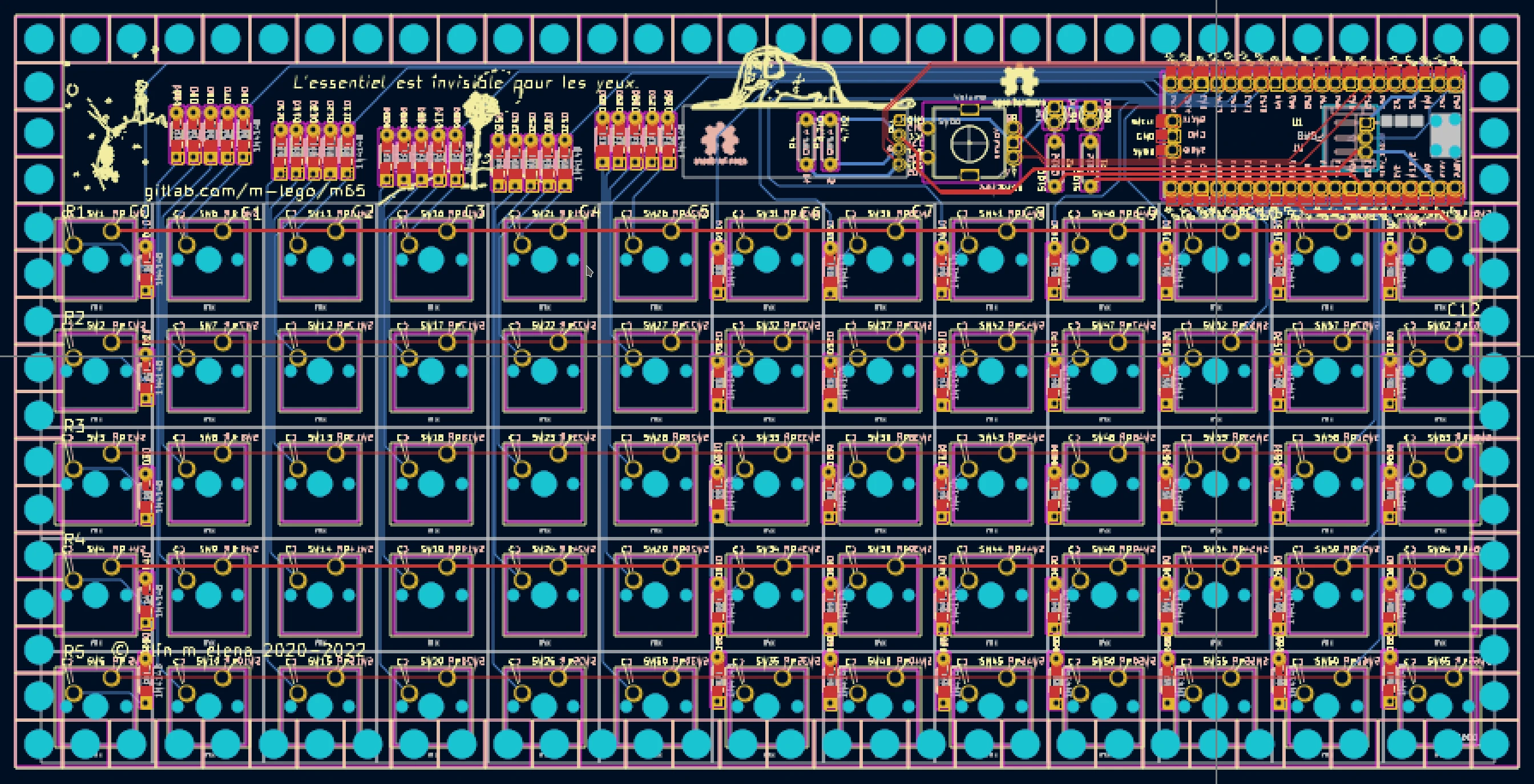
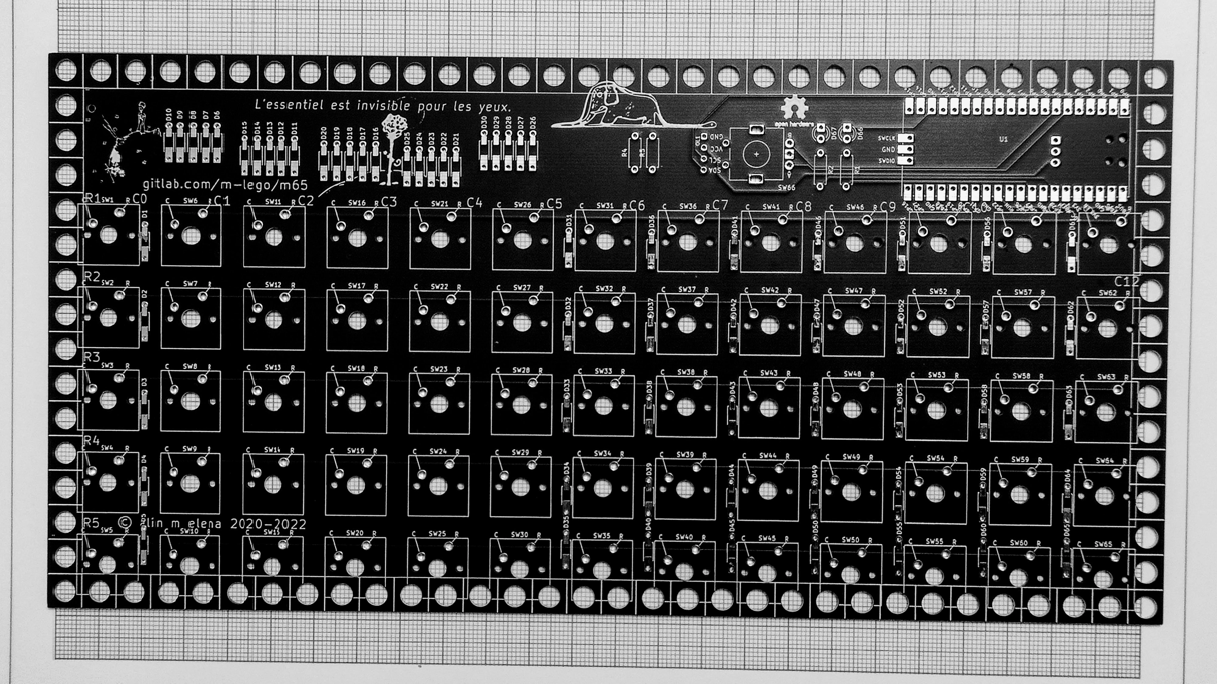
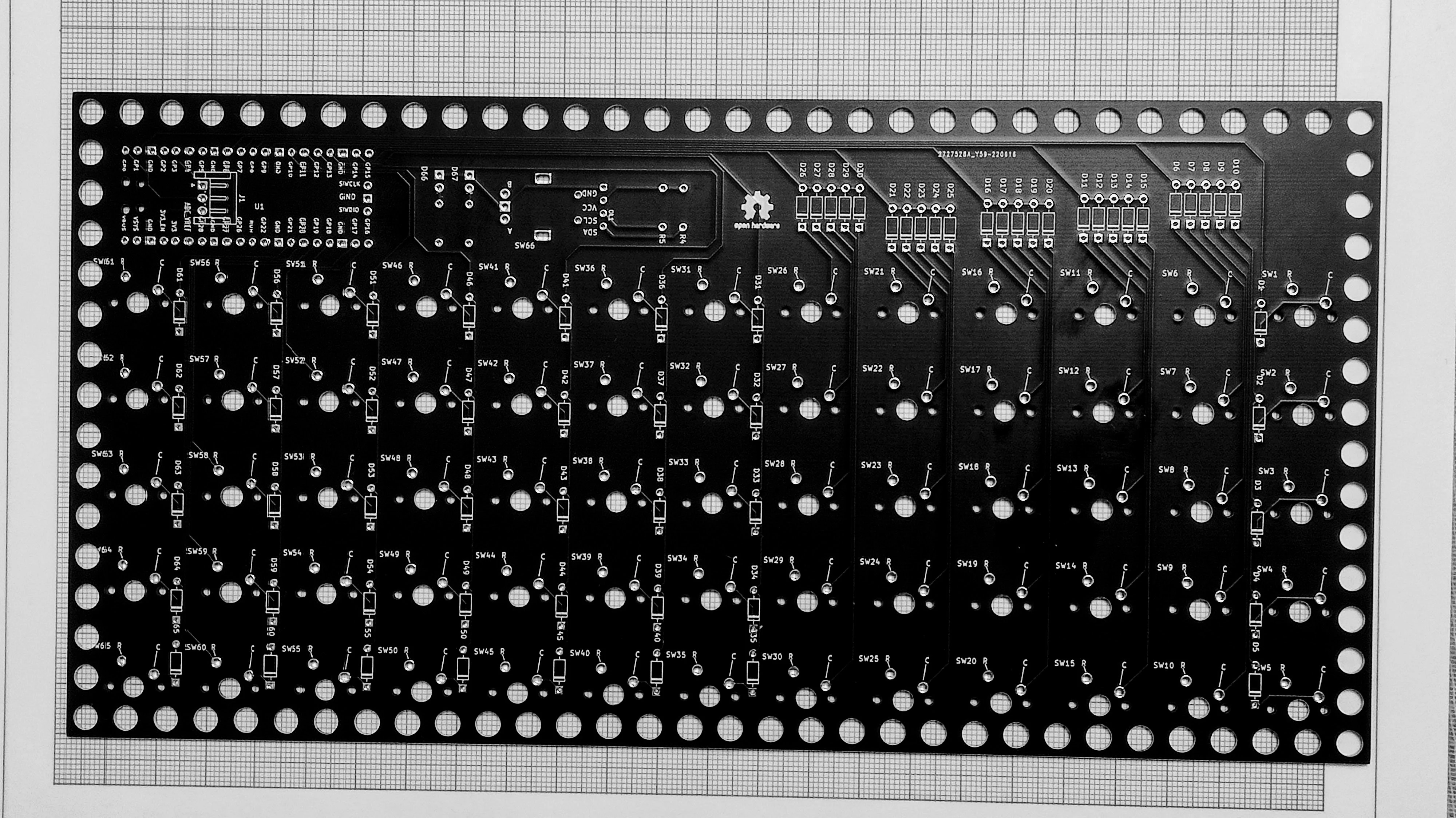
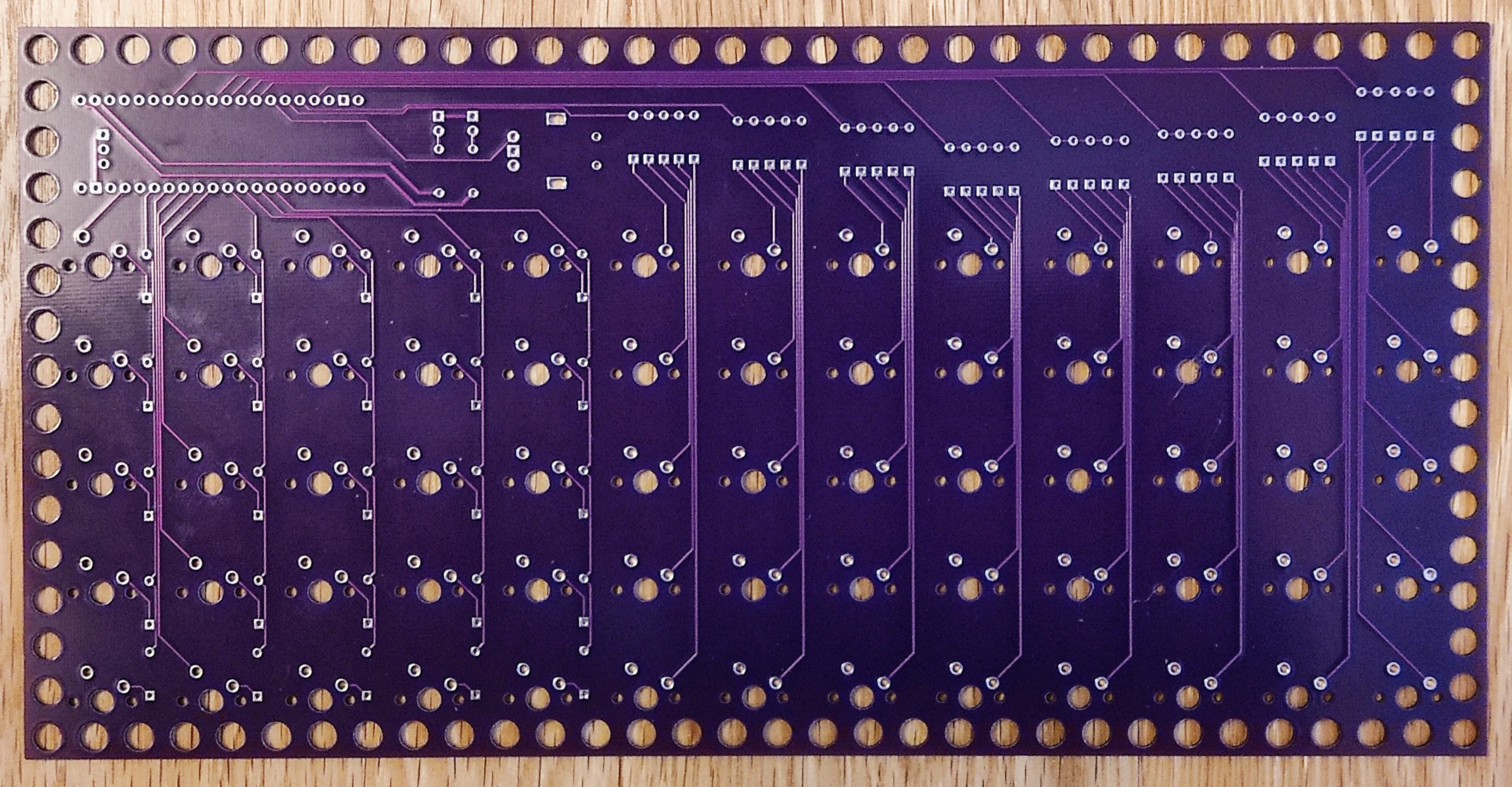
the pcb for rev9
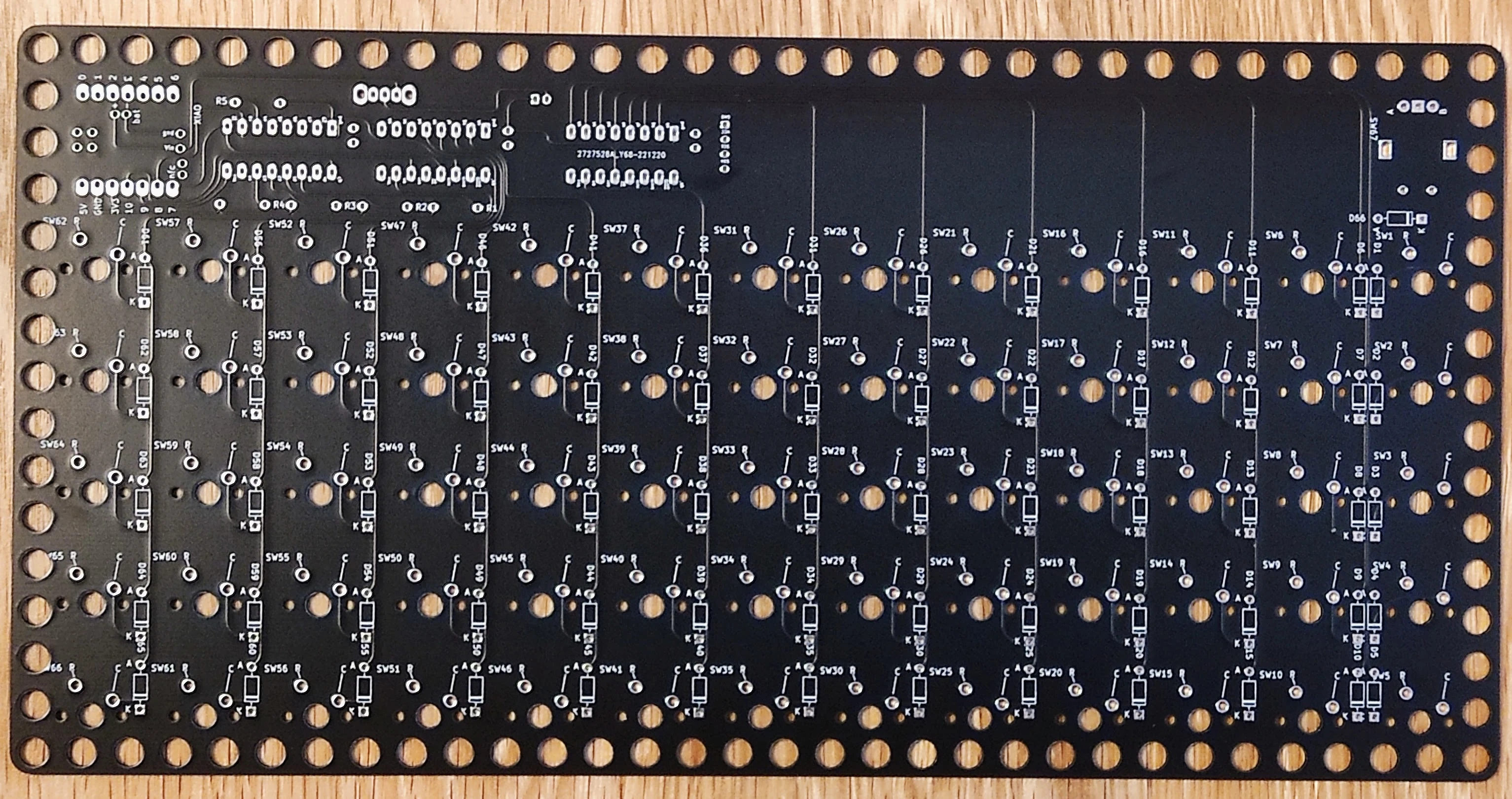
rev 7/8
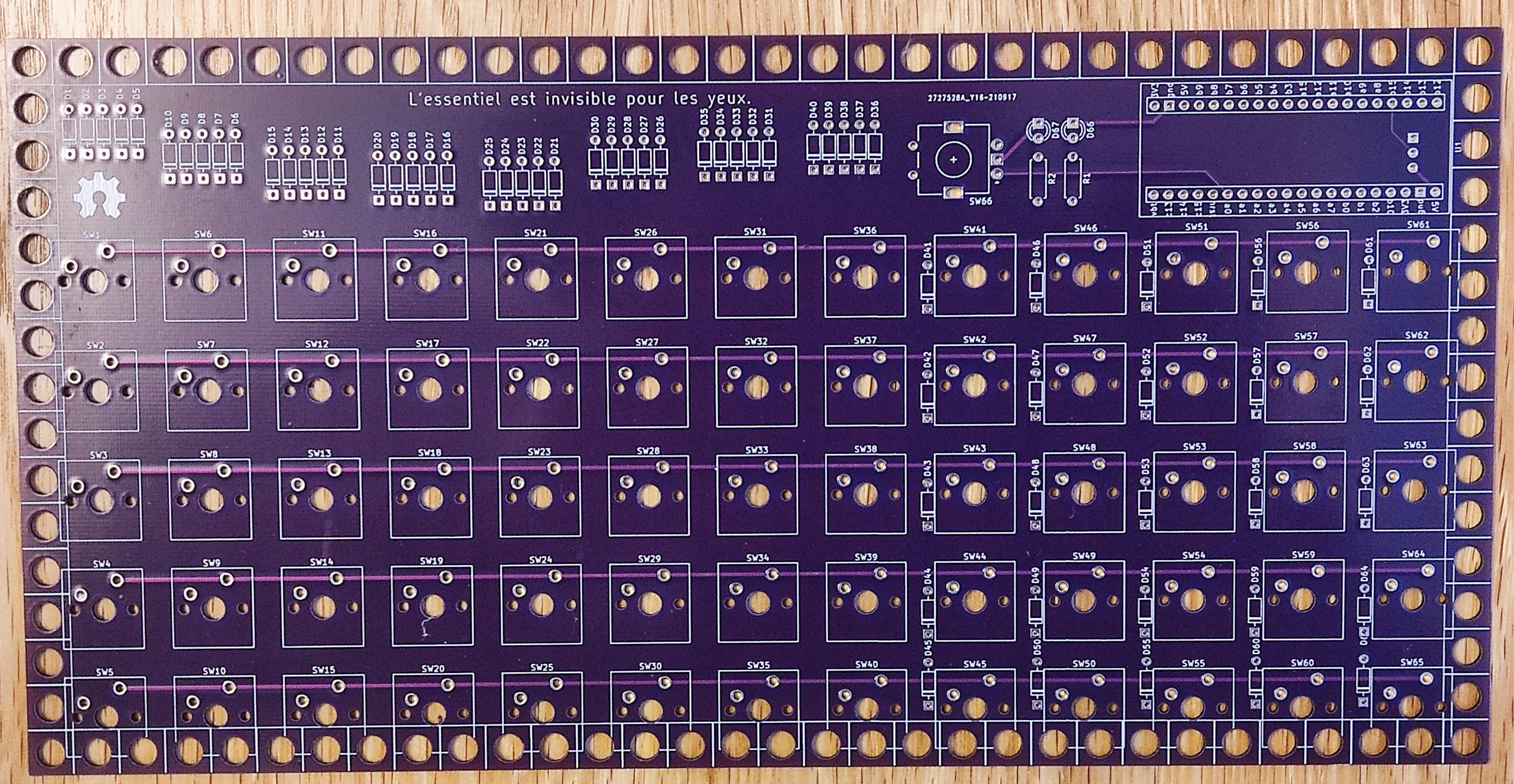
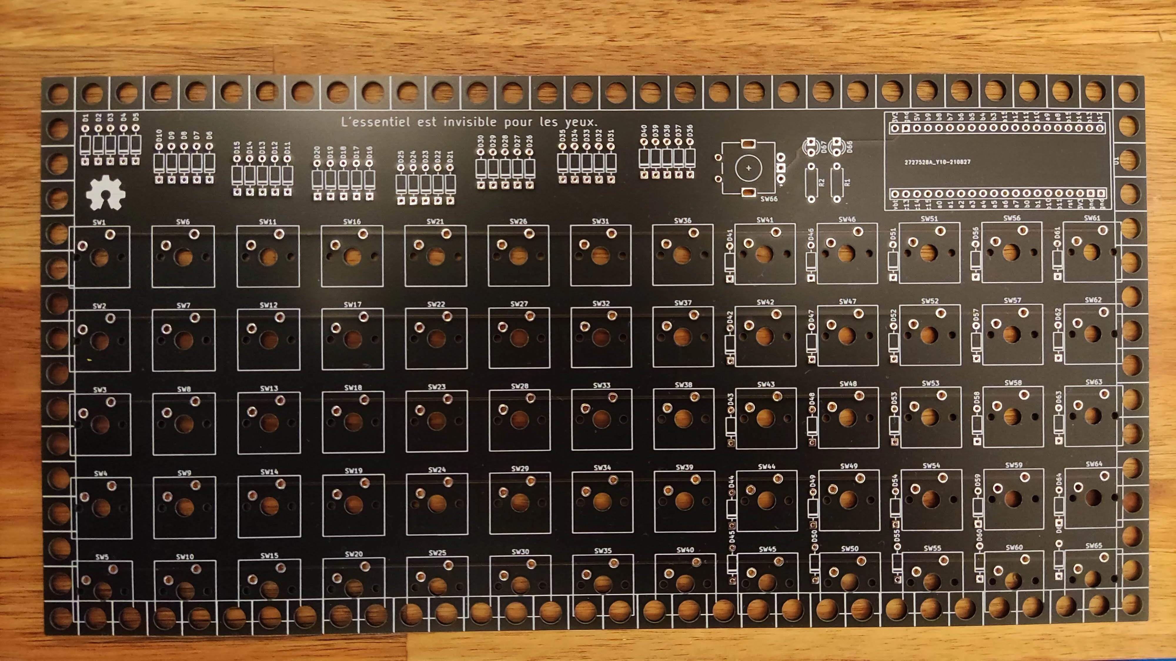
the pcb for rev 7/8
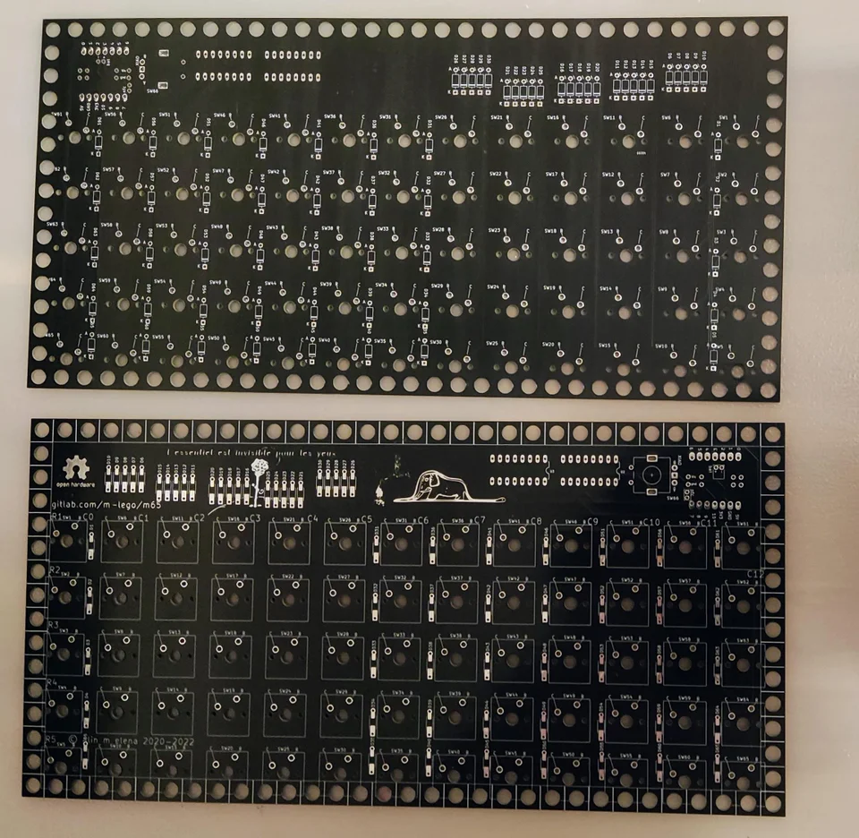

rev 5/6
the pcb for rev5/6
the real pcb
rev 4
version (4) stm32f401 from we act
rev 3
stm32f401 from we act
rev 2
version (2)
rev 1
the pcb (version 1)

gerbers
gerbers ready to be printed at jlcpcb are available
full kicad project if you want to generate your own or modify is available here to get a specific revision see below... please note the head of the default branch is always work in progress.
kicad
  git clone https://gitlab.com/m-lego/m65.git
  cd m65
  git checkout revision11
  git clone https://gitlab.com/m-lego/m65.git
  cd m65
  git checkout revision10
  git clone https://gitlab.com/m-lego/m65.git
  cd m65
  git checkout revision9
  git clone https://gitlab.com/m-lego/m65.git
  cd m65
  git checkout revision7
  git clone https://gitlab.com/m-lego/m65.git
  cd m65
  git checkout revision5
  git clone https://gitlab.com/m-lego/m65.git
  cd m65
  git checkout rev7
firmware
is qmk or zmk, I assume you already have qmk environment configured. can be donloaded, depending on the revision from list below or build by yourself
zmk
rev7,rev5 and rev4 support zmk
- firmware/mlego5x13_rev7-seeeduino_xiao_ble-zmk.uf2
- firmware/mlego5x13_rev7-seeeduino_xiao_rp2040-zmk.uf2
- firmware/mlego5x13_rev4-blackpill_f401ce-zmk.uf2
- firmware/mlego5x13_rev5-rpi_pico-zmk.uf2
you can get the latest firmware from the repo actiona just look for Build mlego workflow and the latest successful artefacts.
source for is available
qmk
- firmware/mlego_m65_rev11_default_knob.uf2
- firmware/mlego_m65_rev11_uk_knob.uf2
- firmware/mlego_m65_rev11_uk_knob_eink.uf2
- firmware/mlego_m65_rev10_default_knob.uf2
- firmware/mlego_m65_rev10_uk_knob.uf2
- firmware/mlego_m65_rev9_default_knob.uf2
- firmware/mlego_m65_rev9_uk_knob.uf2
- firmware/mlego_m65_rev7_default.uf2
- firmware/mlego_m65_rev7_uk.uf2
- firmware/mlego_m65_rev6_default.uf2
- firmware/mlego_m65_rev6_uk.uf2
- firmware/mlego_m65_rev5_default.uf2
- firmware/mlego_m65_rev5_uk.uf2
- firmware/mlego_m65_rev4_default.uf2
- firmware/mlego_m65_rev4_uk.uf2
- firmware/mlego_m65_rev3_default.uf2
- firmware/mlego_m65_rev3_uk.uf2
you can get the latest firmware from the repo actiona just look for the latest successful artefacts.
git
qmk build instructions
  # oled version
  git clone --recurse-submodules -b mlego_dev https://github.com/alinelena/qmk_firmware.git qmk-alin
  cd qmk-alin
  qmk compile -kb mlego/m65/rev11 -km uk_knob
  qmk compile -kb mlego/m65/rev11 -km default_knob


  #or
  make mlego/m65/rev11:uk_knob
  make mlego/m65/rev11:default_knob
  # copy the resulting uf2 on the mcu as per instructions.

  # eink version

  git clone --recurse-submodules -b mlego_eink https://github.com/alinelena/qmk_firmware.git qmk-alin
  cd qmk-alin
  qmk compile -kb mlego/m65/rev11 -km uk_knob
  git clone --recurse-submodules -b mlego_dev https://github.com/alinelena/qmk_firmware.git qmk-alin
  cd qmk-alin
  qmk compile -kb mlego/m65/rev10 -km uk_knob
  qmk compile -kb mlego/m65/rev10 -km default_knob


  #or
  make mlego/m65/rev10:uk_knob
  make mlego/m65/rev10:default_knob
  # copy the resulting uf2 on the mcu as per instructions.
  git clone --recurse-submodules -b mlego_dev https://github.com/alinelena/qmk_firmware.git qmk-alin
  cd qmk-alin
  qmk compile -kb mlego/m65/rev9 -km uk_knob
  qmk compile -kb mlego/m65/rev9 -km default_knob


  #or
  make mlego/m65/rev9:uk_knob
  make mlego/m65/rev9:default_knob
  # copy the resulting uf2 on the mcu as per instructions.
  git clone --recurse-submodules -b mlego_dev https://github.com/alinelena/qmk_firmware.git qmk-alin
  cd qmk-alin
  qmk compile -kb mlego/m65/rev7 -km uk
  qmk compile -kb mlego/m65/rev7 -km default


  #or
  make mlego/m65/rev7:uk
  make mlego/m65/rev7:default
  # copy the resulting uf2 on the mcu as per instructions.
  git clone --recurse-submodules -b mlego_dev https://github.com/alinelena/qmk_firmware.git qmk-alin
  cd qmk-alin
  qmk compile -kb mlego/m65/rev5 -km uk
  qmk compile -kb mlego/m65/rev6 -km uk


  #or
  make mlego/m65/rev5:uk
  make mlego/m65/rev6:uk
  # copy the resulting uf2 on the mcu as per instructions.
  git clone --recurse-submodules https://github.com/qmk/qmk_firmware.git
  cd qmk_firmware
  make mlego/m65/rev4:uk

  #for latest version

  git clone --recurse-submodules -b mlego https://github.com/alinelena/qmk_firmware.git qmk-alin
  cd qmk-alin
  qmk compile -kb mlego/m65/rev4 -km uk

  #or
  make mlego/m65/rev4:uk
  #copy the resulting uf2 on the mcu as per instructions.
  # you can use also stm32f401 from we act

  git clone --recurse-submodules https://github.com/qmk/qmk_firmware.git
  cd qmk_firmware
  make mlego/m65/rev3:uk
  make mlego/m65/rev3:uk:flash
  # you can use also gdf303 from we act aka bluepill plus  https://github.com/WeActTC/BluePill-Plus

  git clone --recurse-submodules https://github.com/qmk/qmk_firmware.git
  cd qmk_firmware
  make mlego/m65/rev2:uk
  make mlego/m65/rev2:uk:flash
  git clone --recurse-submodules https://github.com/qmk/qmk_firmware.git
  cd qmk_firmware
  make mlego/m65/rev1:uk
  make mlego/m65/rev1:uk:flash
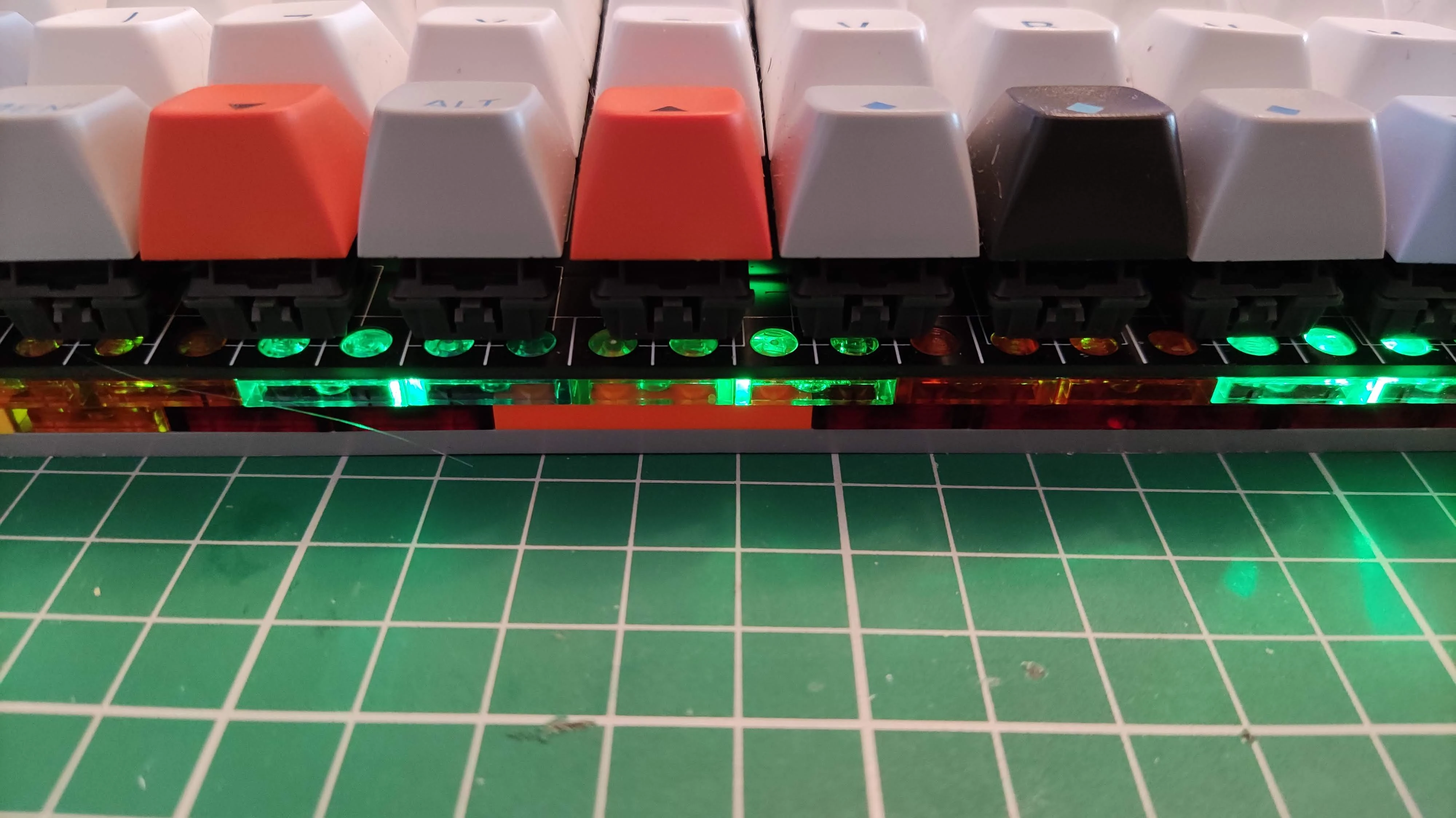
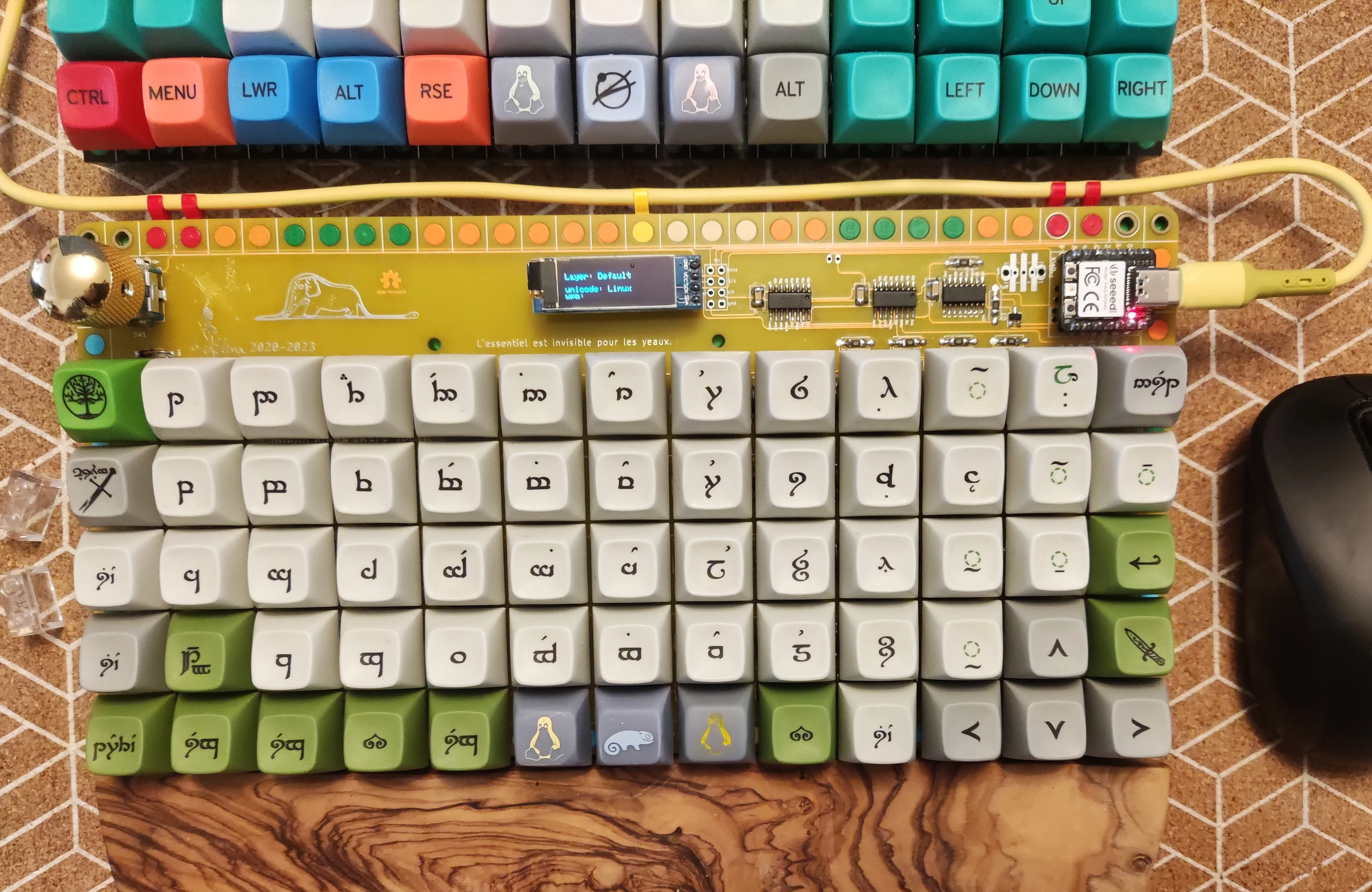
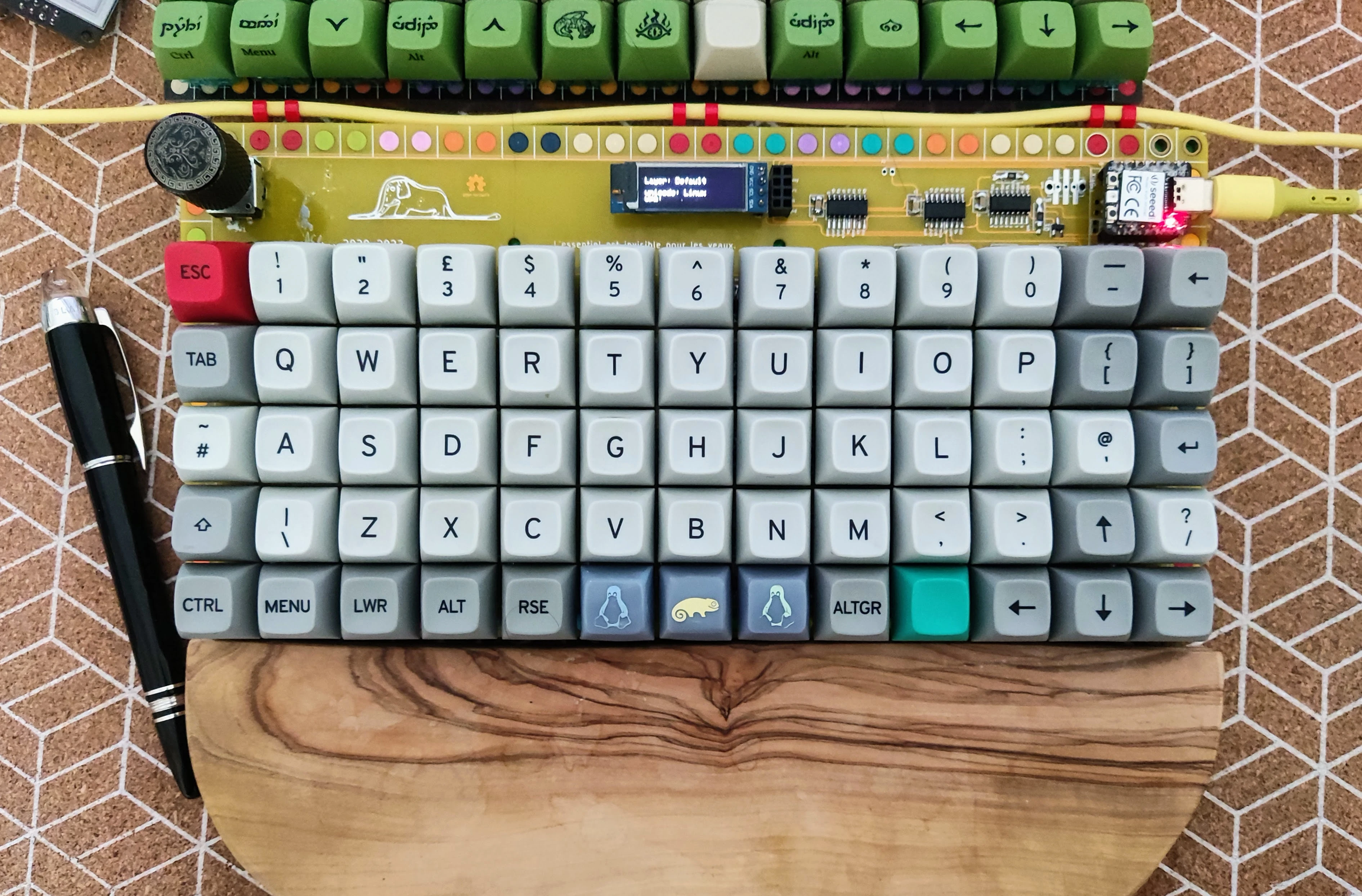
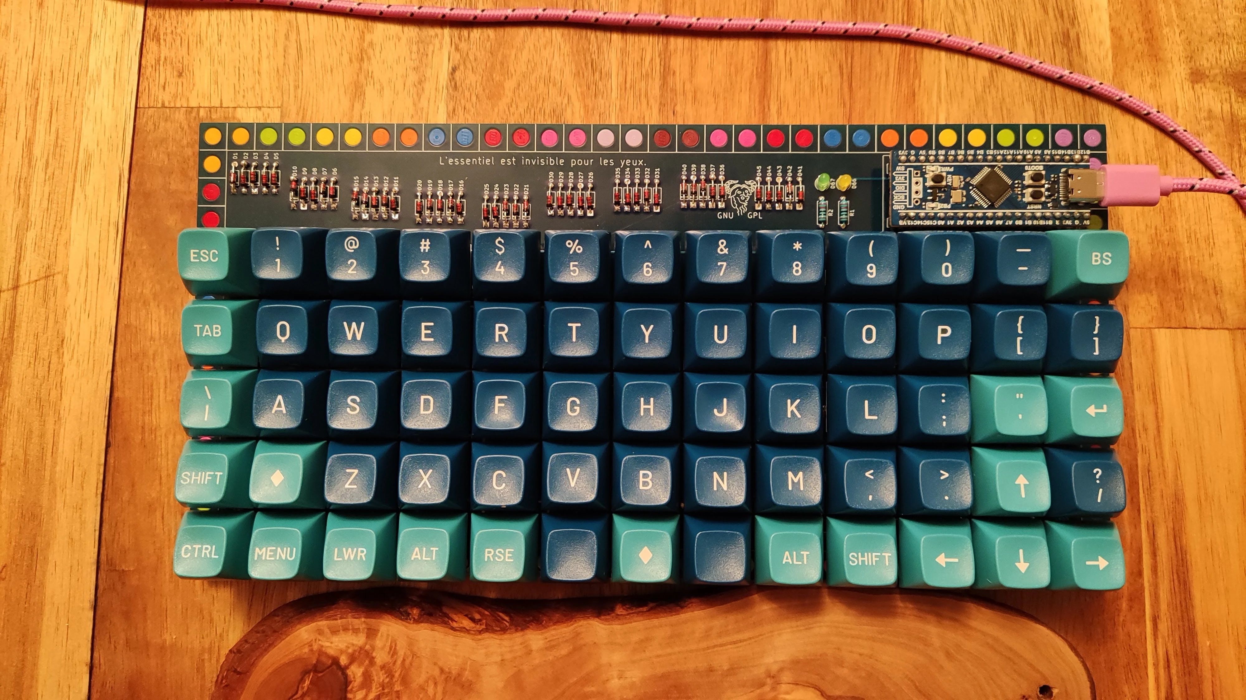
pictures
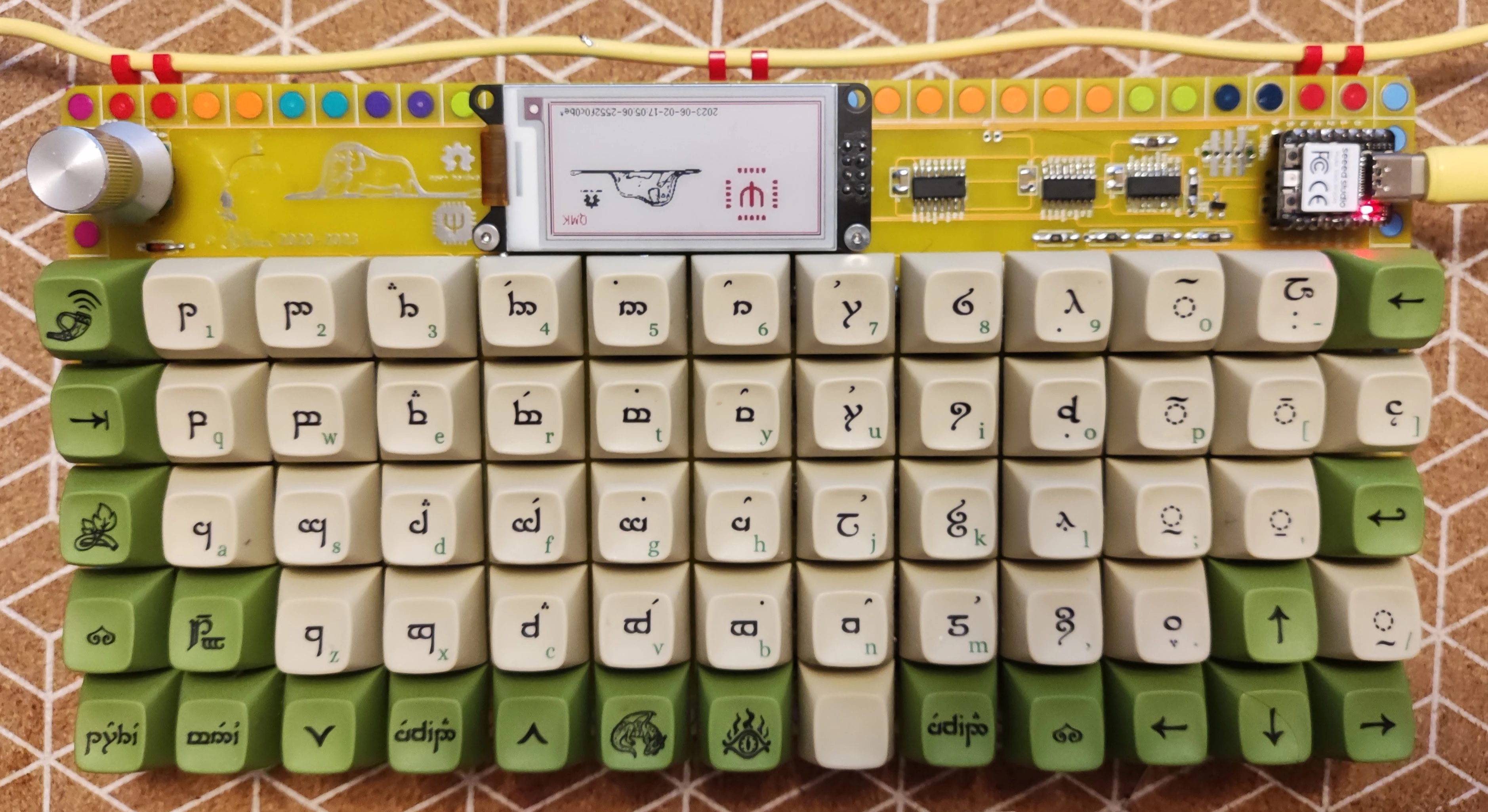
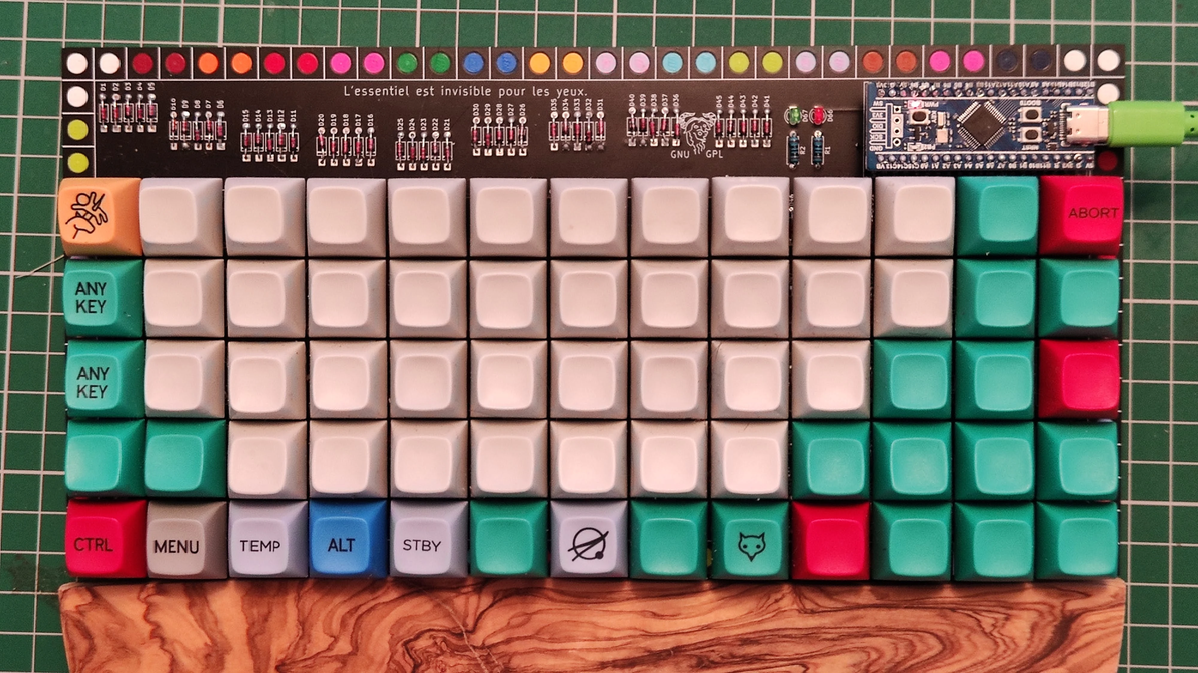
revision 11
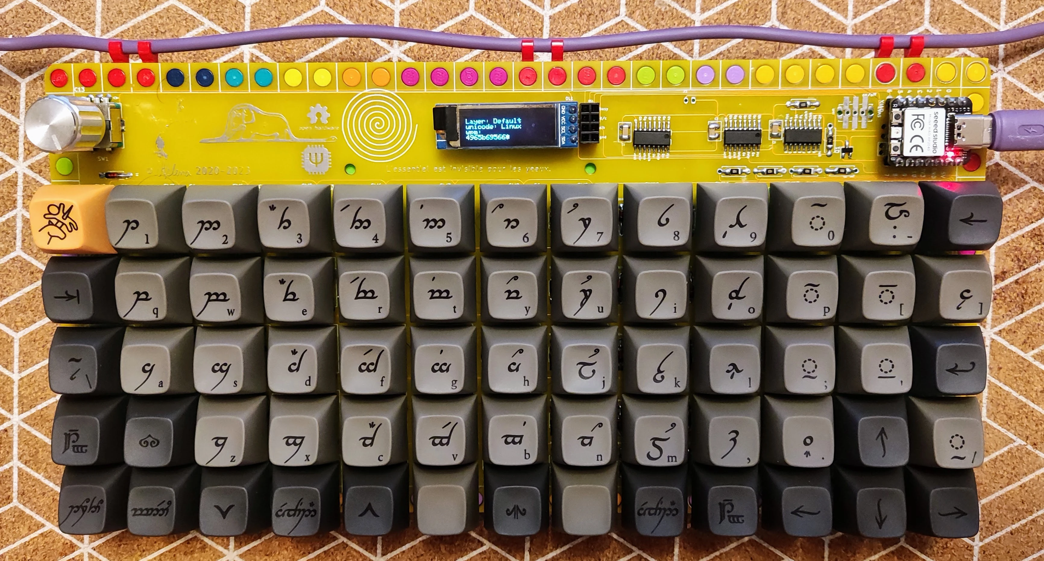
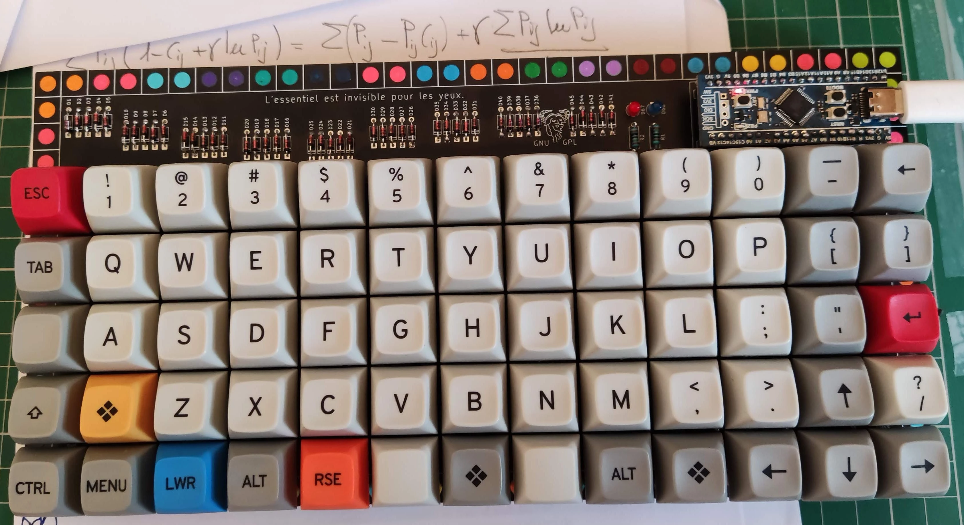
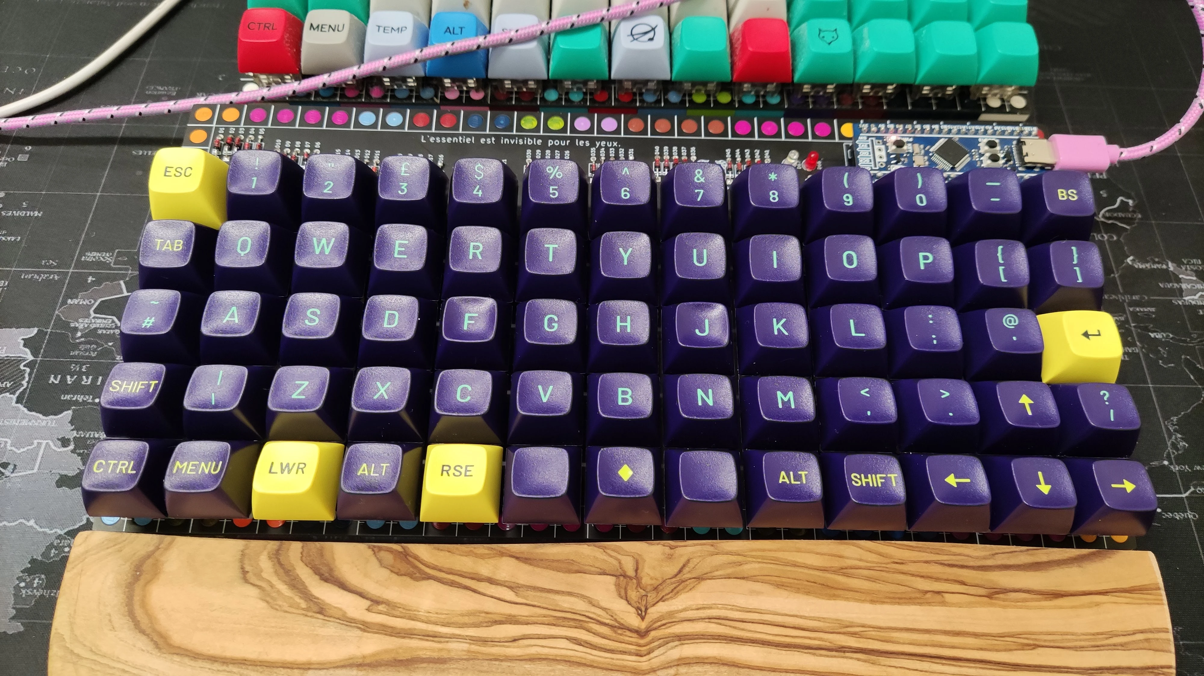
revision 10
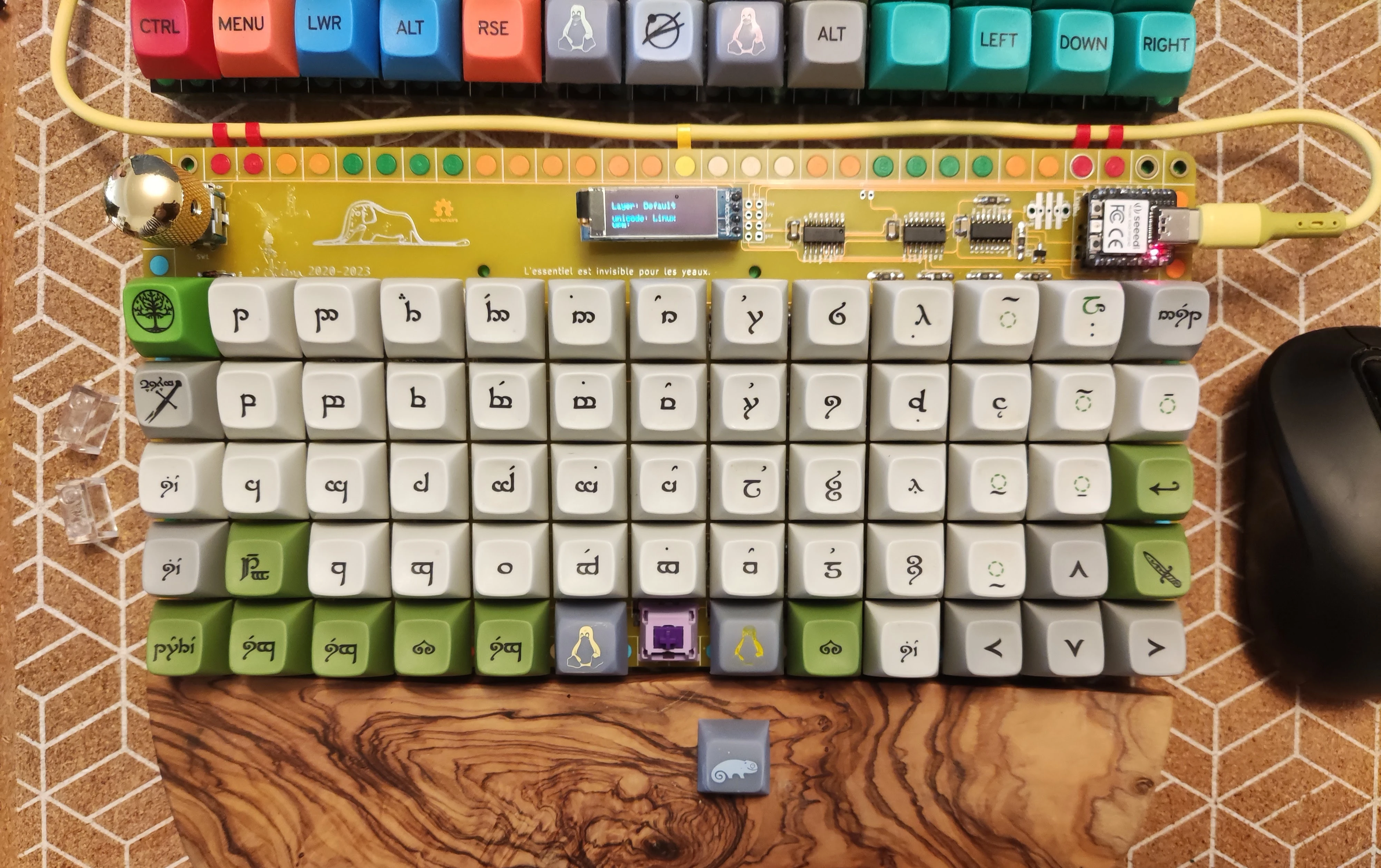
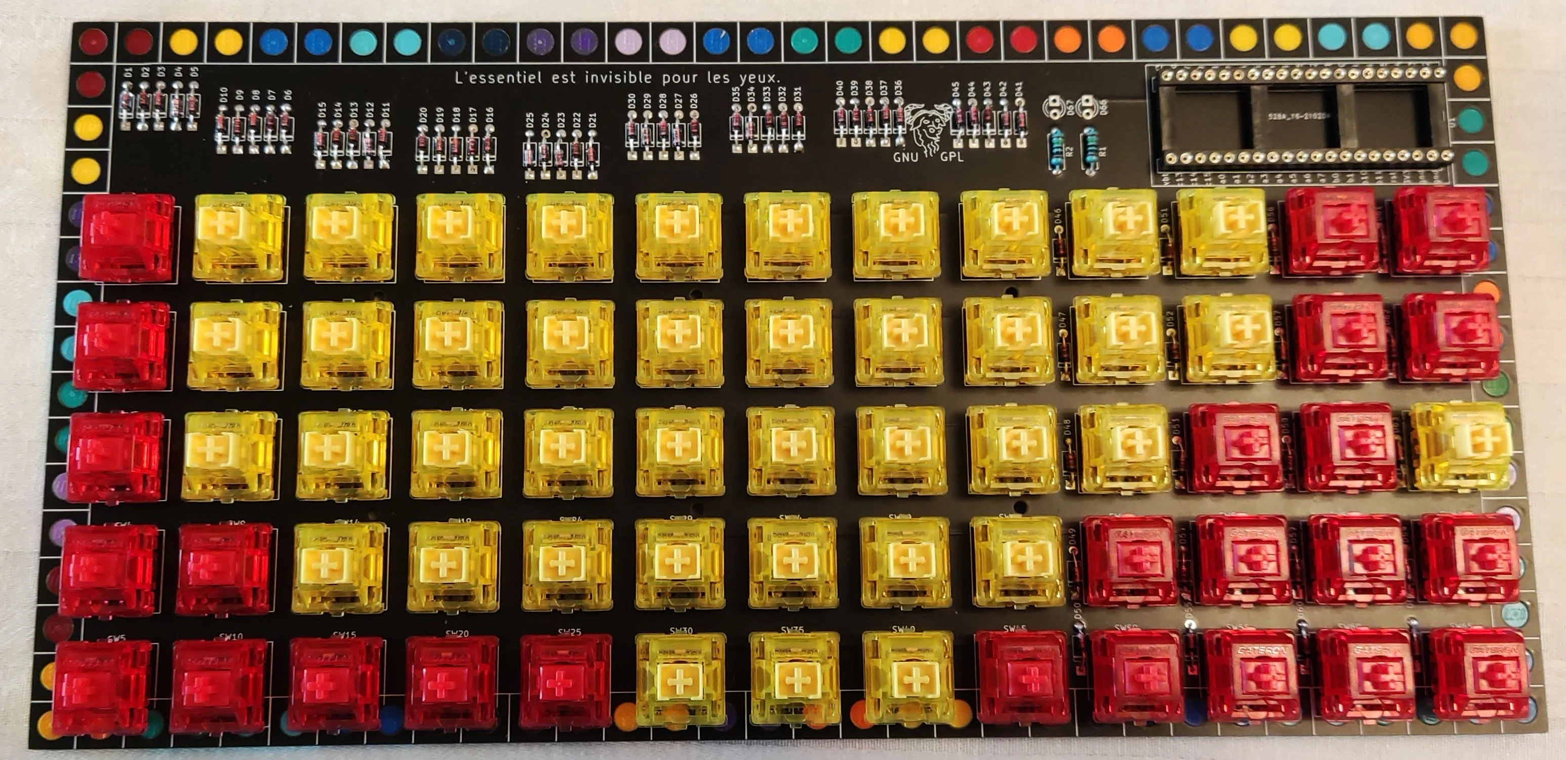
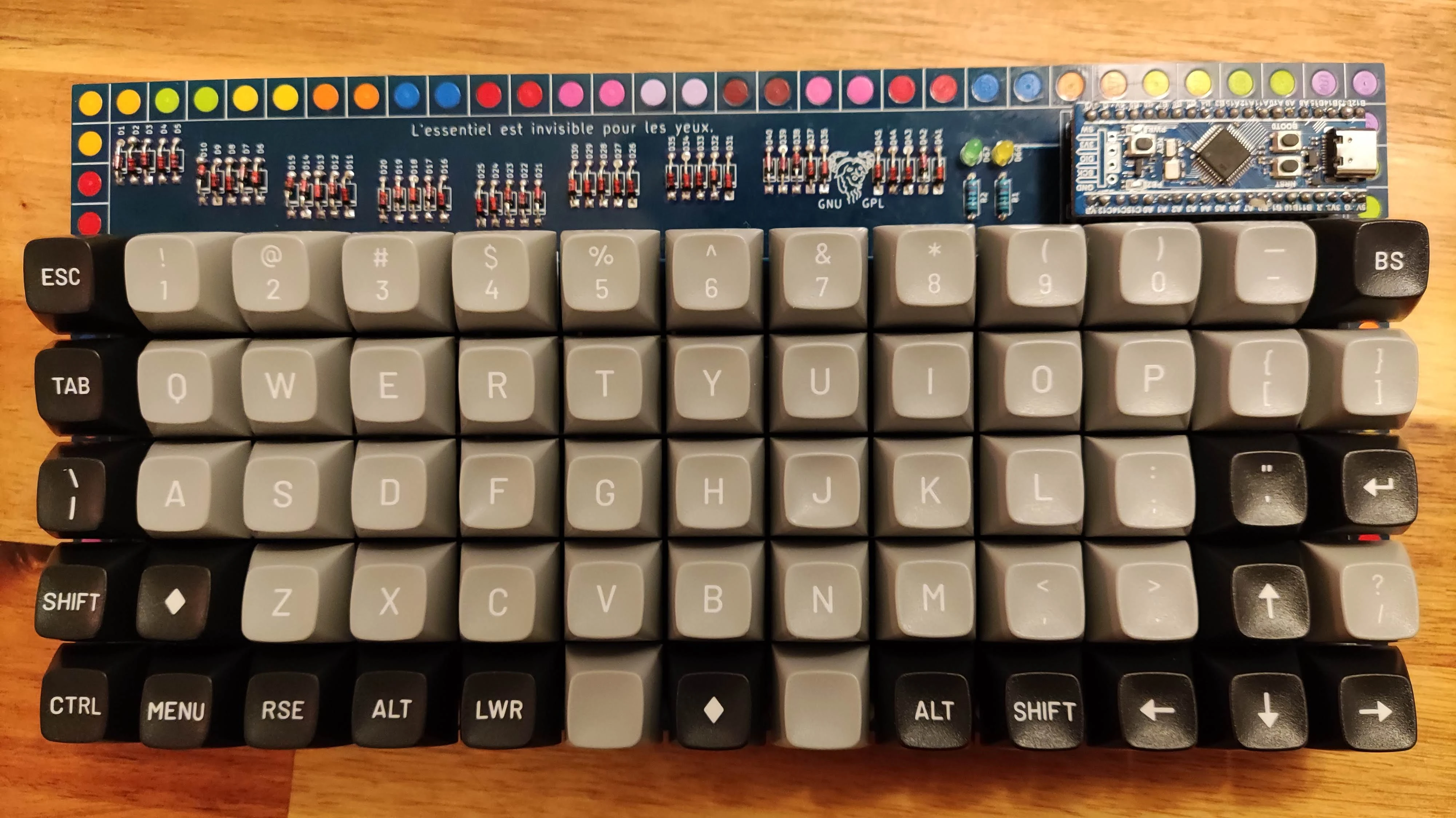
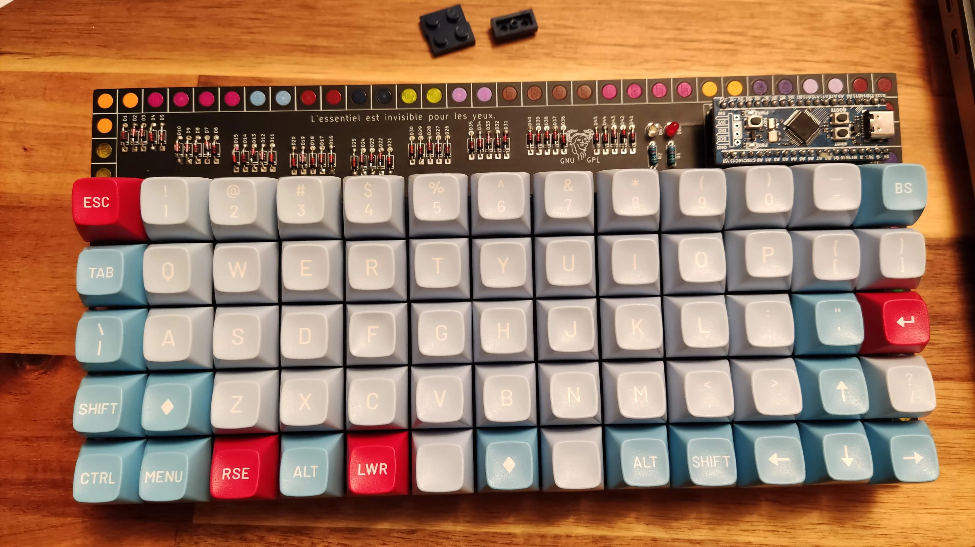
revision 9
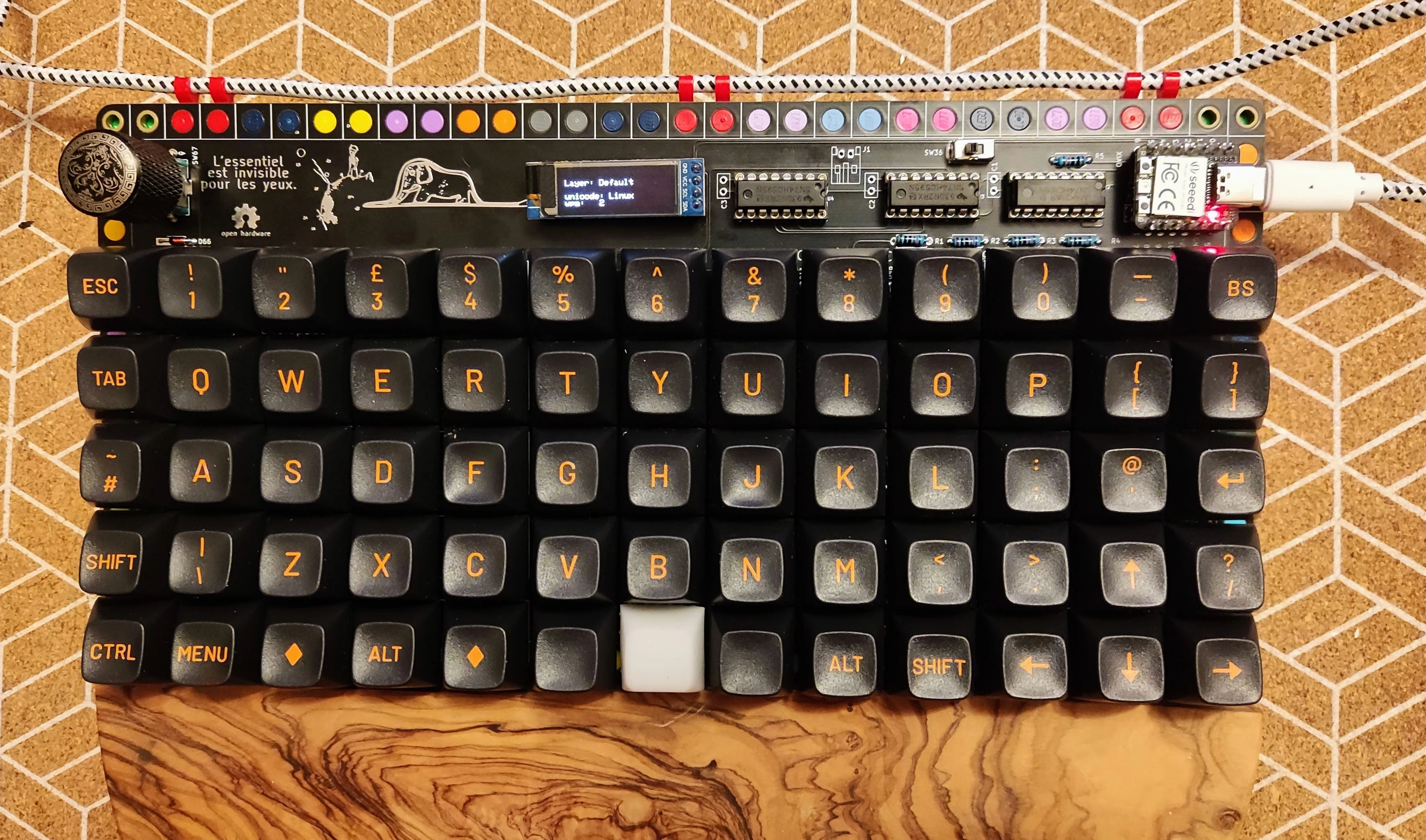
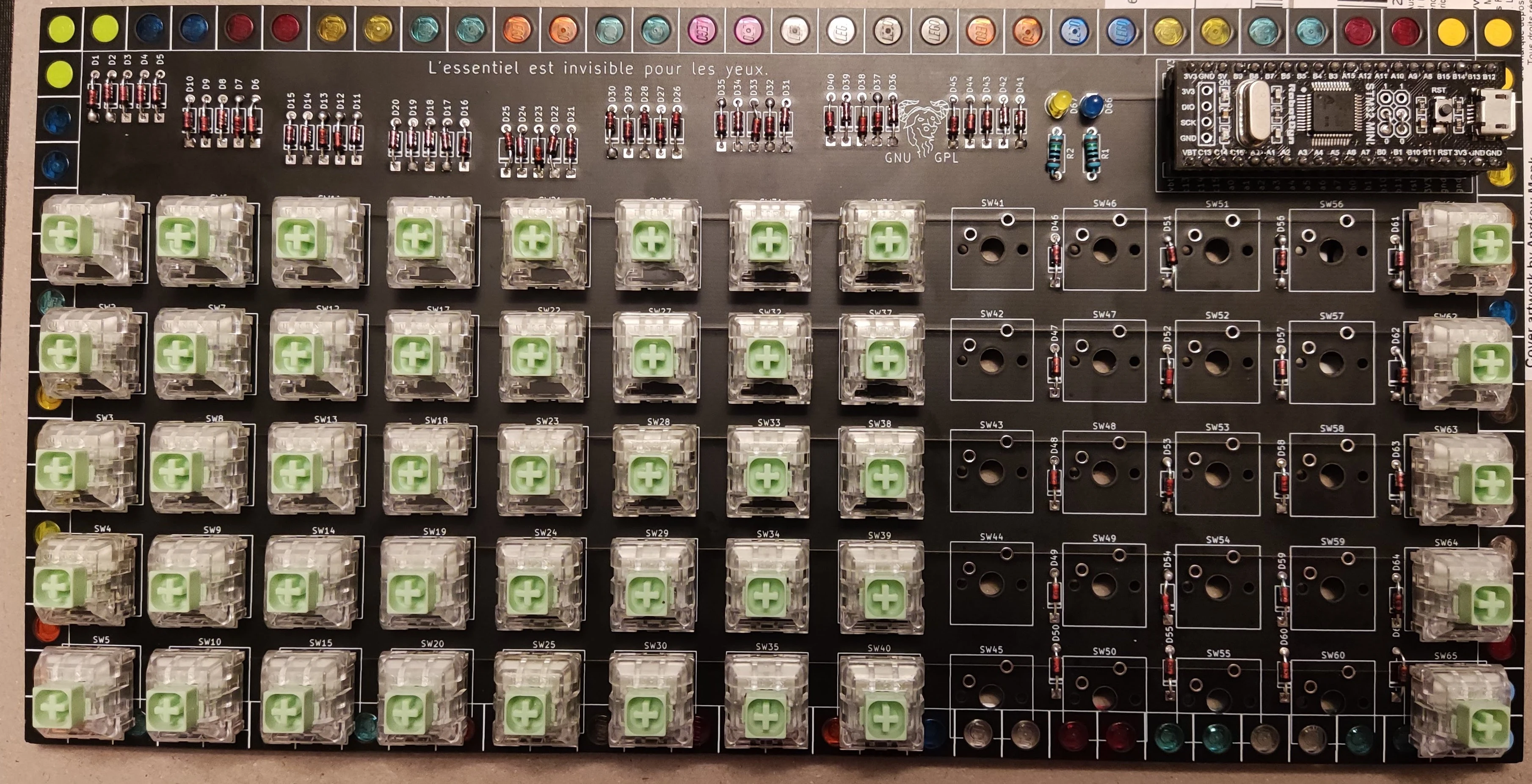
revision 8
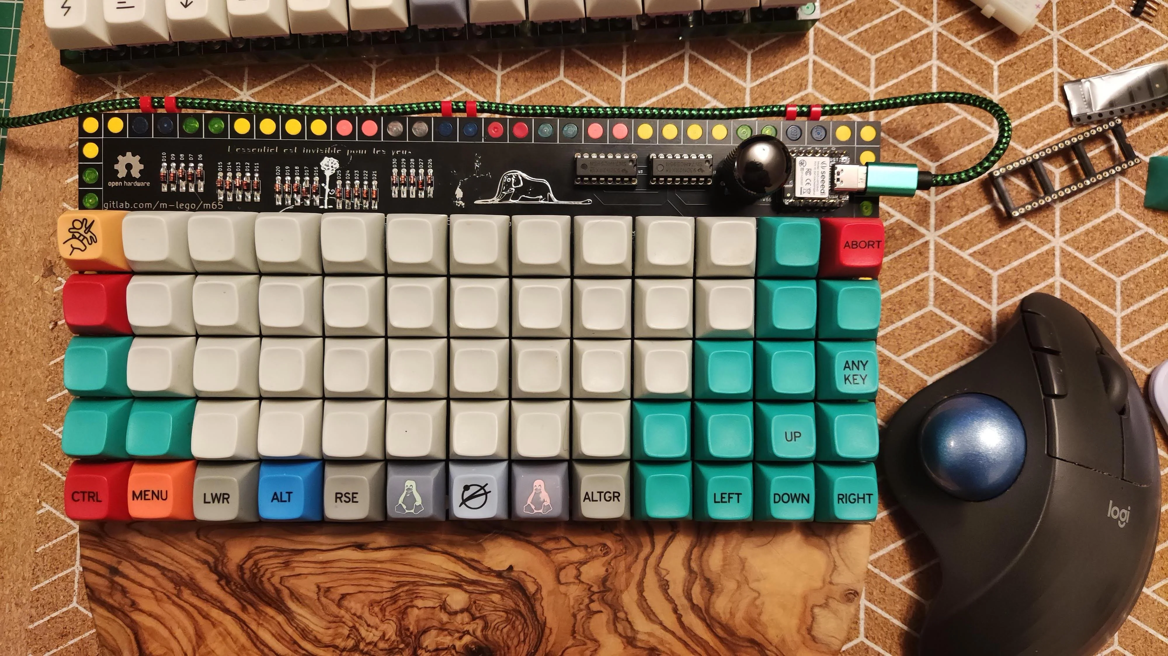
revisions 7
revision 6
with rp2040 usb-c, raspberry pico clone
revision 5
original pico
revision 4
revision 3
revision 2
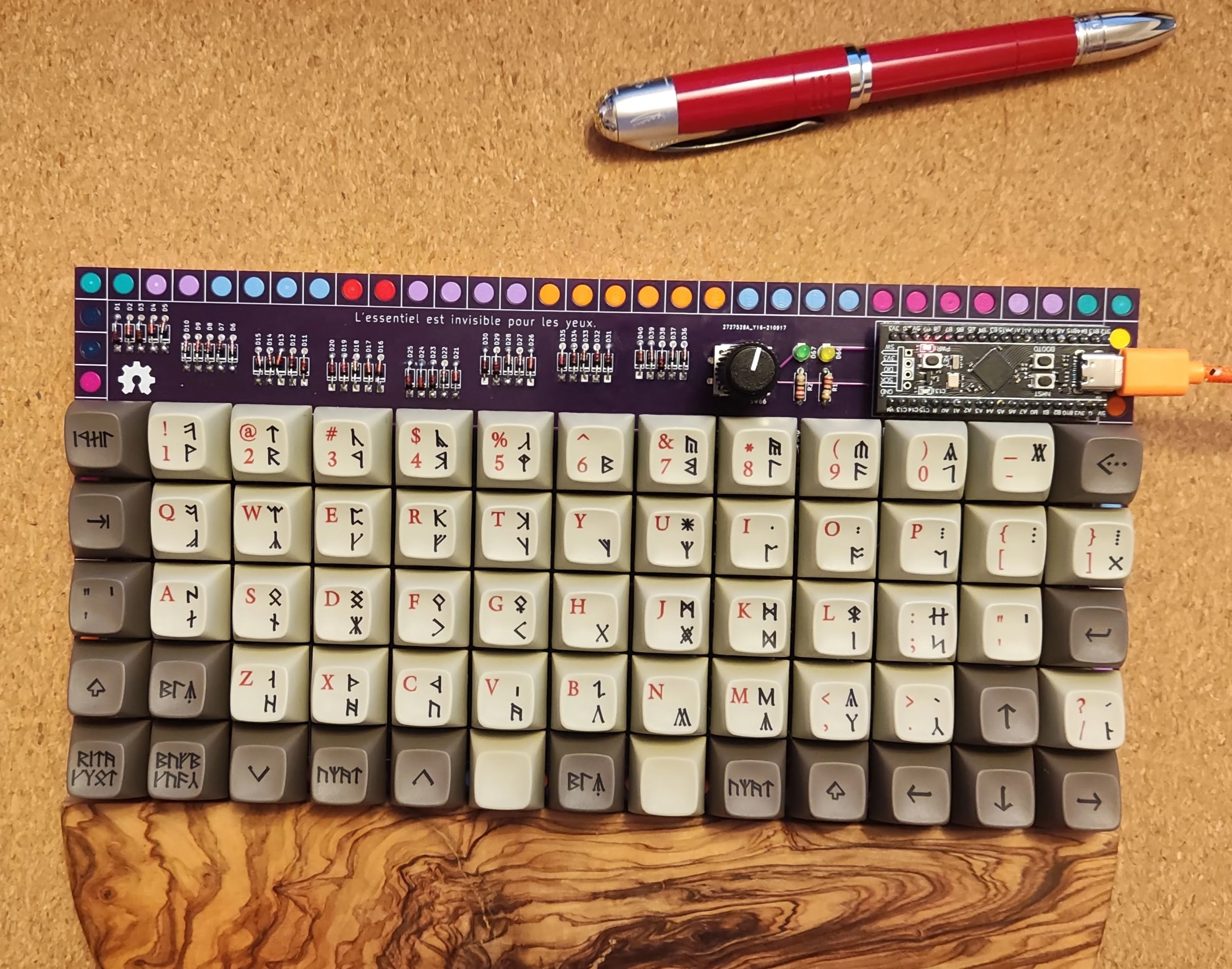
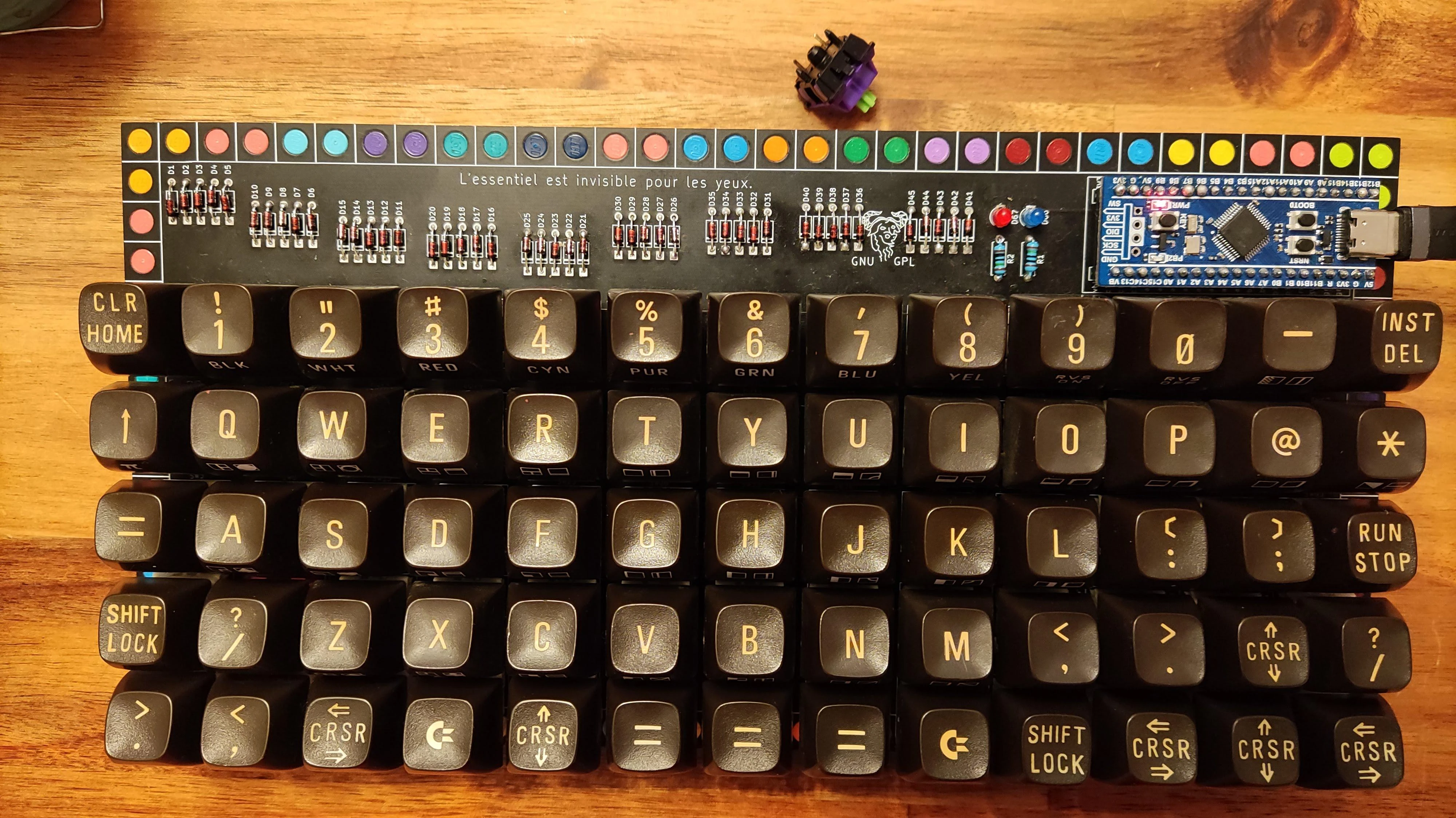
keyboard no 14 (commodore c64 harvest keycaps with mx adapters)
revision 1
keyboard no 2 (mt3 susuwatari, kailh crystal jade)
other
keyboard no 1 (mt3 tty bleached, kailh crystal royal)
keyboard no 2 (mt3 susuwatari, kailh crystal jade)
keyboard no 3 (mt3 tty, kailh crystal royal)

keyboard no 4 (tbd, novelkeys blueberry in process of re-springing)
keyboard no 5 (tbd, gateron ink v2 yellow and red)
keyboard no 6 (kailh crystal jades with click bar removed... )
keyboard no 7 (gateron whites and /dev/tty)
keyboard no 8 (frankenstein switches linears with mt3 camillo)
keyboard no 9 (mt3 2048)
keyboard no 10 (mt3 dasher)
keyboard no 11 (mt3 cyber)
keyboard no 12 (mt3 3277)
keyboard no 13 (mt3 fairlane)
keyboard no 15 (mt3 camillo, eva 02)
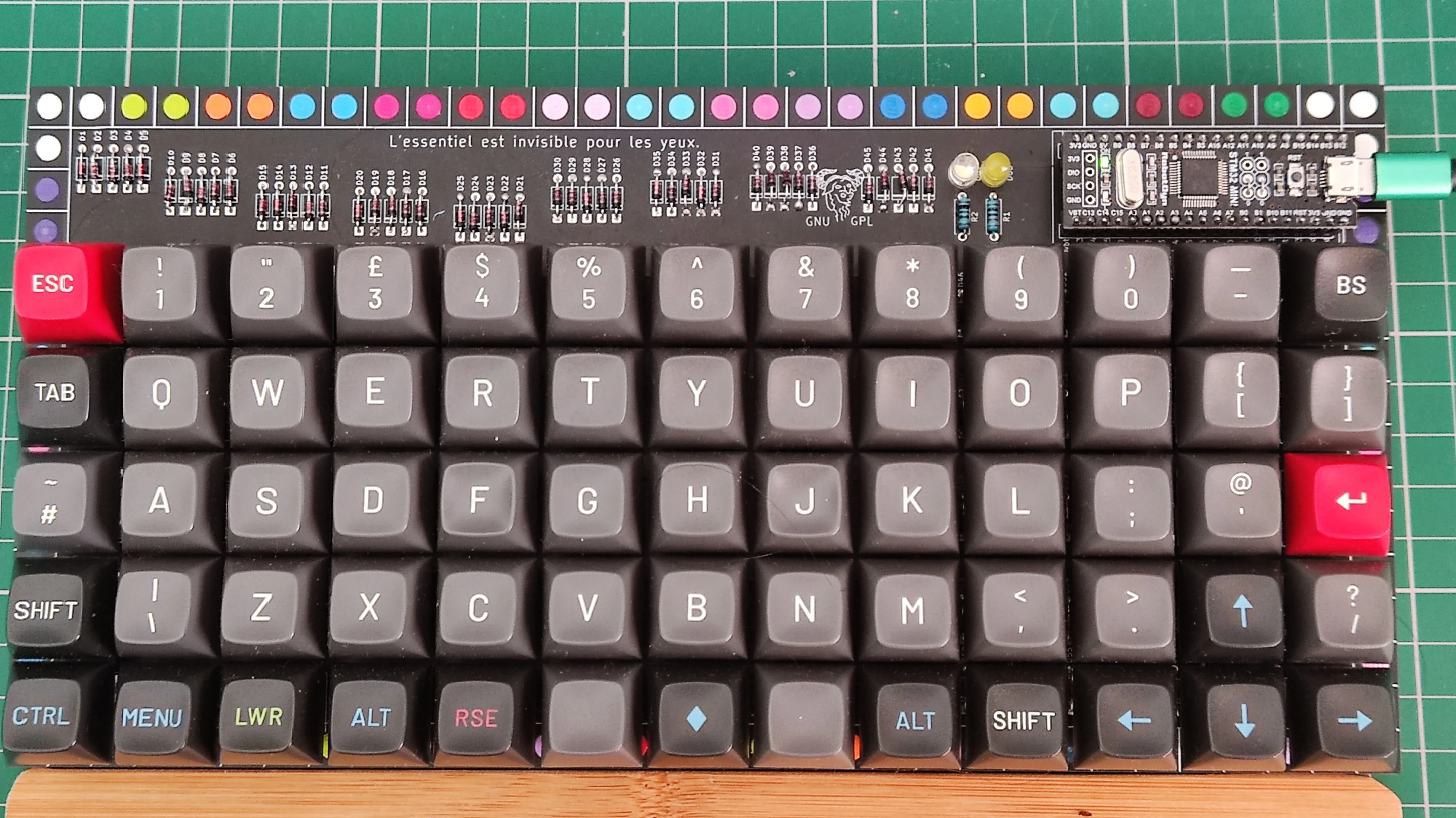
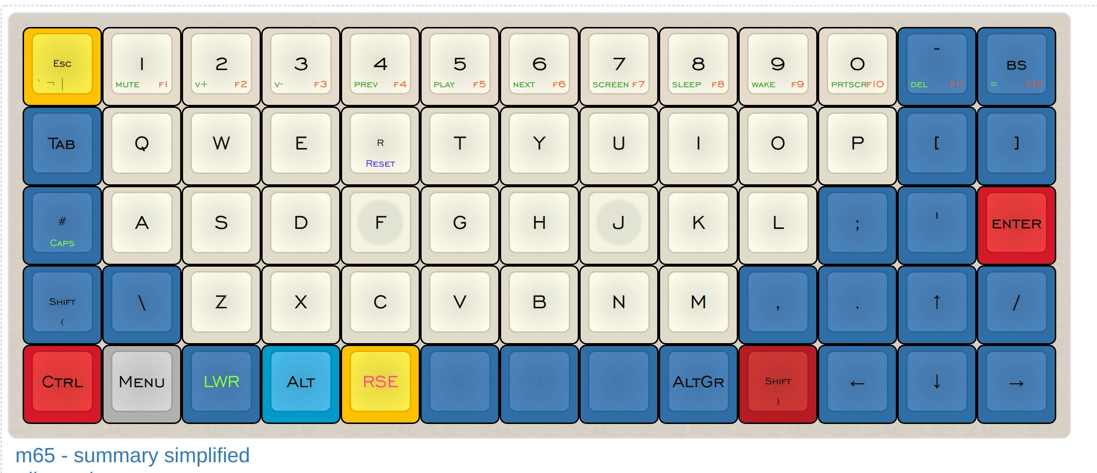
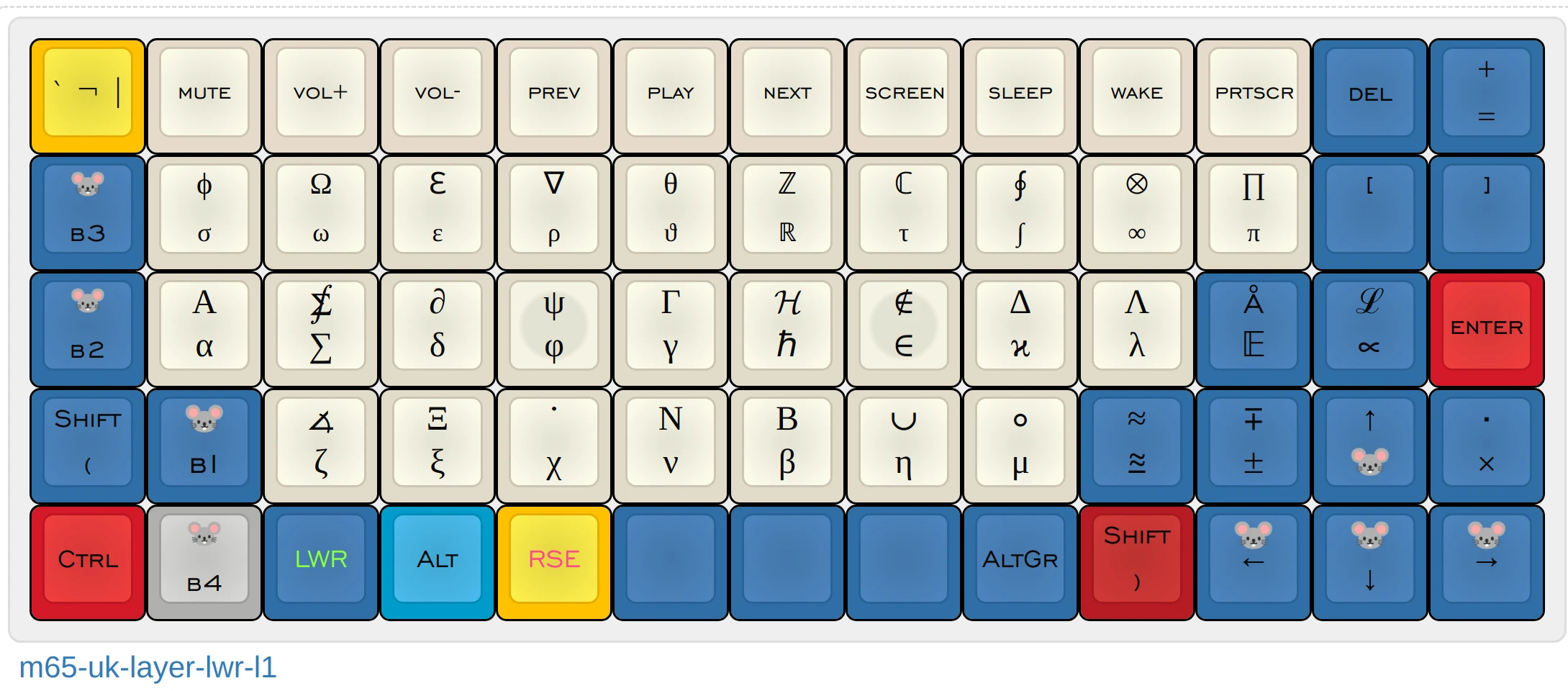
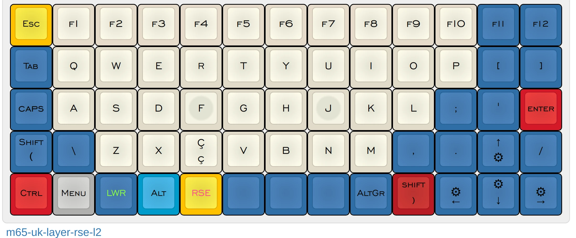
keymaps/layout
layout is bellow, but since is qmk can be whatever one likes.
pins
rev11 seeeduino xiao rp2040
tba
rev10 seeeduino xiao rp2040
tba
rev9 seeeduino xiao rp2040
ShiftRegister SN74HC595N

1
QB |1    16| VCC
QC |2    15| QA
QD |3    14| SER data
QE |4    13| OE
QF |5    12| RCLK latch
QG |6    11| SRCLK clock
QH |7    10| SRCLR
 G |8    9 | QH*

2
QB |1    16| VCC
QC |2    15| QA
QD |3    14| SER
QE |4    13| OE
QF |5    12| RCLK
QG |6    11| SRCLK
QH |7    10| SRCLR
 G |8    9 | QH*

shift register 74HC165N

3
nPL |1    16| VCC
 CP |2    15| nCE
 D4 |3    14| D3
 D5 |4    13| D2
 D6 |5    12| D1
 D7 |6    11| D0
nQ7 |7    10| DS
  G |8    9 | Q7
| Rows | C0 | C1 | C2 | C3 | C4 | C5 | C6 | C7 | C8 | C9 | C10 | C11 | C12 | C13 | Pins |
|---|---|---|---|---|---|---|---|---|---|---|---|---|---|---|---|
| R0 | Esc | 1 | 2 | 3 | 4 | 5 | 6 | 7 | 8 | 9 | 0 | - | Bksp | MUTE | 3D0 |
| R1 | Tab | q | w | e | r | t | y | u | i | o | p | [ | ] | X* | 3D1 |
| R2 | # | a | s | d | f | g | h | j | k | l | ; | ' | Enter | X* | 3D2 |
| R3 | Shift | \ | z | x | c | v | b | n | m | , | . | Up | / | X* | 3D3 |
| R4 | Ctrl | Menu | Lower | Alt | Raise | Space | Space | Space | AltGr | Shift | Left | Down | Right | X* | 3D4 |
| 2QB | 2QC | 2QD | 2QE | 2QF | 2QG | 2QH | 2QA | 1QH | 1QG | 1QF | 1QE | 1QA | 1QD |
X* not connected in circuit
Encoders
- Pad_A: GP27
- Pad_B: GP26
OLED
- I2C SCL: GP7
- I2C SDA: GP6
Leds
| Leds | Pin |
|---|---|
| CAPS_LOCK | GP25 |
| Lower | GP16 |
| Raise | GP17 |
| RGB DI | GP12 |
| RGB on | GP11 |
^ only on rp2040
** 74HC595N **
- data out MOSI: 11 - GP3
- latch: 8 - GP1
- clock: 9 - GP2
** 74HC165N **
- latch: 8 - GP1
- clock: 9 - GP2
- data in MISO: 10 - GP4
SPI_DIVISOR 8
rev7 seeeduino xiao rp2040/ble/ble sense
| Rows | C0 | C1 | C2 | C3 | C4 | C5 | C6 | C7 | C8 | C9 | C10 | C11 | C12 | Pins |
|---|---|---|---|---|---|---|---|---|---|---|---|---|---|---|
| R0 | Esc | 1 | 2 | 3 | 4 | 5 | 6 | 7 | 8 | 9 | 0 | - | Bksp | D0 GP26 |
| R1 | Tab | q | w | e | r | t | y | u | i | o | p | [ | ] | D1 GP27 |
| R2 | # | a | s | d | f | g | h | j | k | l | ; | ' | Enter | D2 GP28 |
| R3 | Shift | \ | z | x | c | v | b | n | m | , | . | Up | / | D3 GP29 |
| R4 | Ctrl | Menu | Lower | Alt | Raise | Space | Space | Space | AltGr | Shift | Left | Down | Right | D4 GP6 |
| 2QH | 2QG | 2QF | 2QE | 2QD | 2QC | 2QB | 2QA | 1QH | 1QG | 1QF | 1QE | 1QA |
Encoders
- Pad_A: D5 GP7
- Pad_B: D6 GP0
Leds
| Leds | Pin |
|---|---|
| CAPS_LOCK | GP25 |
| Lower | GP16 |
| Raise | GP17 |
| RGB DI^ | GP12 |
| RGB on^ | GP11 |
^ only on rp2040
** 74HC595N **
- data: 11 - D10 GP3
- latch: 8 - D7 GP1
- clock: 9 - D8 GP2
SPI_DIVISOR 32
Pins and leds rev5 rp2040 Raspberry Pico, Teenstar
| Rows | C0 | C1 | C2 | C3 | C4 | C5 | C6 | C7 | C8 | C9 | C10 | C11 | C12 | Pins |
|---|---|---|---|---|---|---|---|---|---|---|---|---|---|---|
| R0 | Esc | 1 | 2 | 3 | 4 | 5 | 6 | 7 | 8 | 9 | 0 | - | Bksp | GP22 |
| R1 | Tab | q | w | e | r | t | y | u | i | o | p | [ | ] | GP16 |
| R2 | # | a | s | d | f | g | h | j | k | l | ; | ' | Enter | GP18 |
| R3 | Shift | \ | z | x | c | v | b | n | m | , | . | Up | / | GP19 |
| R4 | Ctrl | Menu | Lower | Alt | Raise | Space | Space | Space | AltGr | Shift | Left | Down | Right | GP20 |
| GP1 | GP6 | GP7 | GP8 | GP9 | GP15 | GP14 | GP13 | GP12 | GP11 | GP10 | GP17 | GP21 |
Encoders
- Pad_A: GP4
- Pad_B: GP5
Oled
- SDA: GP2
- SCL/SCK: GP3
Leds
| Leds | Pin |
|---|---|
| NUM_LOCK | GP28 |
| CAPS_LOCK | GP25 |
| SCROLL_LOCK | GP27 |
| RBG_DI | GP0 |
Pins and leds rev6 rp2040 weact
| Rows | C0 | C1 | C2 | C3 | C4 | C5 | C6 | C7 | C8 | C9 | C10 | C11 | C12 | Pins |
|---|---|---|---|---|---|---|---|---|---|---|---|---|---|---|
| R0 | Esc | 1 | 2 | 3 | 4 | 5 | 6 | 7 | 8 | 9 | 0 | - | Bksp | GP22 |
| R1 | Tab | q | w | e | r | t | y | u | i | o | p | [ | ] | GP16 |
| R2 | # | a | s | d | f | g | h | j | k | l | ; | ' | Enter | GP18 |
| R3 | Shift | \ | z | x | c | v | b | n | m | , | . | Up | / | GP19 |
| R4 | Ctrl | Menu | Lower | Alt | Raise | Space | Space | Space | AltGr | Shift | Left | Down | Right | GP20 |
| GP1 | GP6 | GP7 | GP8 | GP9 | GP15 | GP14 | GP13 | GP12 | GP11 | GP10 | GP17 | GP21 |
Encoders
- Pad_A: GP4
- Pad_B: GP5
Oled
- SDA: GP2
- SCL/SCK: GP3
Leds
| Leds | Pin |
|---|---|
| NUM_LOCK | GP29 |
| CAPS_LOCK | GP25 |
| SCROLL_LOCK | GP28 |
| RBG_DI | GP0 |
- while some pin numbers for leds are different physical positions are the same for both rev5 and rev6
Pins and leds rev4 stm32f401
the pinout is the same for stm32f411
| Rows | C0 | C1 | C2 | C3 | C4 | C5 | C6 | C7 | C8 | C9 | C10 | C11 | C12 | Pins |
|---|---|---|---|---|---|---|---|---|---|---|---|---|---|---|
| R0 | Esc | 1 | 2 | 3 | 4 | 5 | 6 | 7 | 8 | 9 | 0 | - | Bksp | B10 |
| R1 | Tab | q | w | e | r | t | y | u | i | o | p | [ | ] | A5 |
| R2 | # | a | s | d | f | g | h | j | k | l | ; | ' | Enter | A6 |
| R3 | Shift | \ | z | x | c | v | b | n | m | , | . | Up | / | A7 |
| R4 | Ctrl | Menu | Lower | Alt | Raise | Space | Space | Space | AltGr | Shift | Left | Down | Right | B0 |
| B14 | A8 | A10 | A15 | B3 | B4 | B5 | B7 | A1 | A2 | A3 | A4 | B1 |
Encoders
- Pad_A: A0
- Pad_B: B6
Oled
- SDA: B9
- SCL/SCK: B8
Leds
| Leds | Pin |
|---|---|
| NUM_LOCK | B12 |
| CAPS_LOCK | C13 |
| SCROLL_LOCK | B13 |
| RBG_DI | B15 |
Pins and leds rev3 stm32f401
the pinout is the same for stm32f411
| Rows | C0 | C1 | C2 | C3 | C4 | C5 | C6 | C7 | C8 | C9 | C10 | C11 | C12 | Pins |
|---|---|---|---|---|---|---|---|---|---|---|---|---|---|---|
| R0 | Esc | 1 | 2 | 3 | 4 | 5 | 6 | 7 | 8 | 9 | 0 | - | Bksp | B10 |
| R1 | Tab | q | w | e | r | t | y | u | i | o | p | [ | ] | A5 |
| R2 | # | a | s | d | f | g | h | j | k | l | ; | ' | Enter | A6 |
| R3 | Shift | \ | z | x | c | v | b | n | m | , | . | Up | / | A7 |
| R4 | Ctrl | Menu | Lower | Alt | Raise | Space | Space | Space | AltGr | Shift | Left | Down | Right | B0 |
| A10 | A15 | B3 | B4 | B5 | B9 | B8 | B7 | A1 | A2 | A3 | A4 | B1 |
Encoders
- Pad_A: A0
- Pad_B: B6
Leds
| Leds | Pin |
|---|---|
| NUM_LOCK | B12 |
| CAPS_LOCK | C13 |
| SCROLL_LOCK | B13 |
| RBG_DI | B15 |
Pins and leds rev2 GD32F303CCT6
| Rows | C0 | C1 | C2 | C3 | C4 | C5 | C6 | C7 | C8 | C9 | C10 | C11 | C12 | Pins |
|---|---|---|---|---|---|---|---|---|---|---|---|---|---|---|
| R0 | Esc | 1 | 2 | 3 | 4 | 5 | 6 | 7 | 8 | 9 | 0 | - | Bksp | B11 |
| R1 | Tab | q | w | e | r | t | y | u | i | o | p | [ | ] | B0 |
| R2 | # | a | s | d | f | g | h | j | k | l | ; | ' | Enter | B1 |
| R3 | Shift | \ | z | x | c | v | b | n | m | , | . | Up | / | A2 |
| R4 | Ctrl | Menu | Lower | Alt | Raise | Space | Space | Space | AltGr | Shift | Left | Down | Right | A3 |
| A10 | A15 | B3 | B4 | B5 | B9 | B8 | B7 | B6 | C15 | A0 | A7 | B10 |
Encoders
- Pad_A: A8
- Pad_B: A9
Leds
| Leds | Pin |
|---|---|
| NUM_LOCK | B12 |
| CAPS_LOCK | B2 |
| SCROLL_LOCK | B13 |
| RBG_DI | B15 |
Pins and leds rev1 STM/APM32F103C8T6
similar pinout for STM32F303
| Rows | C0 | C1 | C2 | C3 | C4 | C5 | C6 | C7 | C8 | C9 | C10 | C11 | C12 | Pins |
|---|---|---|---|---|---|---|---|---|---|---|---|---|---|---|
| R0 | Esc | 1 | 2 | 3 | 4 | 5 | 6 | 7 | 8 | 9 | 0 | - | Bksp | B11 |
| R1 | Tab | q | w | e | r | t | y | u | i | o | p | [ | ] | B0 |
| R2 | # | a | s | d | f | g | h | j | k | l | ; | ' | Enter | B1 |
| R3 | Shift | \ | z | x | c | v | b | n | m | , | . | Up | / | A2 |
| R4 | Ctrl | Menu | Lower | Alt | Raise | Space | Space | Space | AltGr | Shift | Left | Down | Right | A3 |
| A10 | A15 | B3 | B4 | B5 | B9 | B8 | B7 | B6 | C15 | A0 | A7 | B10 |
Encoders
- Pad_A: A8
- Pad_B: A9
Leds
| Leds | Pin |
|---|---|
| NUM_LOCK | B12 |
| CAPS_LOCK | C13 |
| SCROLL_LOCK | B13 |
| RBG_DI | B15 |
Scan frequencies
these are the scan frequencies as reproted by qmk when you enable DEBUG_MATRIX_SCAN_RATE, see qmk documentation for how to. for each test i use the default matrix
| MCU | revision | Freq 1¹ | Freq 2² |
|---|---|---|---|
| teensy 2 (atmega32u4) | handwire | 1860 | - |
| APM32F103C8T6 (STM32F103) | rev1 | 3427 | - |
| GD32F303CCT6 (STM32F103) | rev2 | 3931 | - |
| STM32F401 | rev 4 | 4681 | 1976 |
| rp2040 pico | rev 5 | 5277 | 2214 |
| rp2040 pico | rev 6 | 5278 | 2202 |
| rp2040 xiao | rev7 | 6162 | - |
| rp2040 xiao | rev 9³ | 4366 | 2125 |
| rp2040 xiao unicode enabled | rev 9 | 3986 | 1924 |
¹ Freq 1 oled is off, wpm is off, rgblight is off, mouse key and extra key also off
² Freq 2 oled is on at all other features
³ rev9 has an extra column compared with previous versions, SPI_DIVISOR is 8 while on rev7 is 32
OLED case
updating oled cause a framatic drop in scanning rate. qmk has an option OLED_UPDATE_INTERVAL to control the interval at which we update the old. All tests were done on rev9 and keymap default and default options for rev9 on, see the firmware for details.
Base line rates are: oled off wpm off - 3760 and oled off, wpm on: 2631. Tested with both 128x32 and 128x64 screens numbers are the same.
| interval [ms] | Frequency |
|---|---|
| 0¹ | 2125 |
| 1 | 3154 |
| 2 | 3629 |
| 3 | 3788 |
| 4 | 3868 |
| 5 | 3915 |
| 10 | 4011 |
| 20 | 4058 |
| 30 | 4075 |
| 50 | 4087 |
| 100 | 4097 |
¹ default value in qmk
two points in here.
- 10 ms seems like a decent scan rate that one can expect, that is 100 fps more than needed for a keyboard oled.
- I do not understand why max frequency obtained is bigger than the baseline (oled off wpm off)