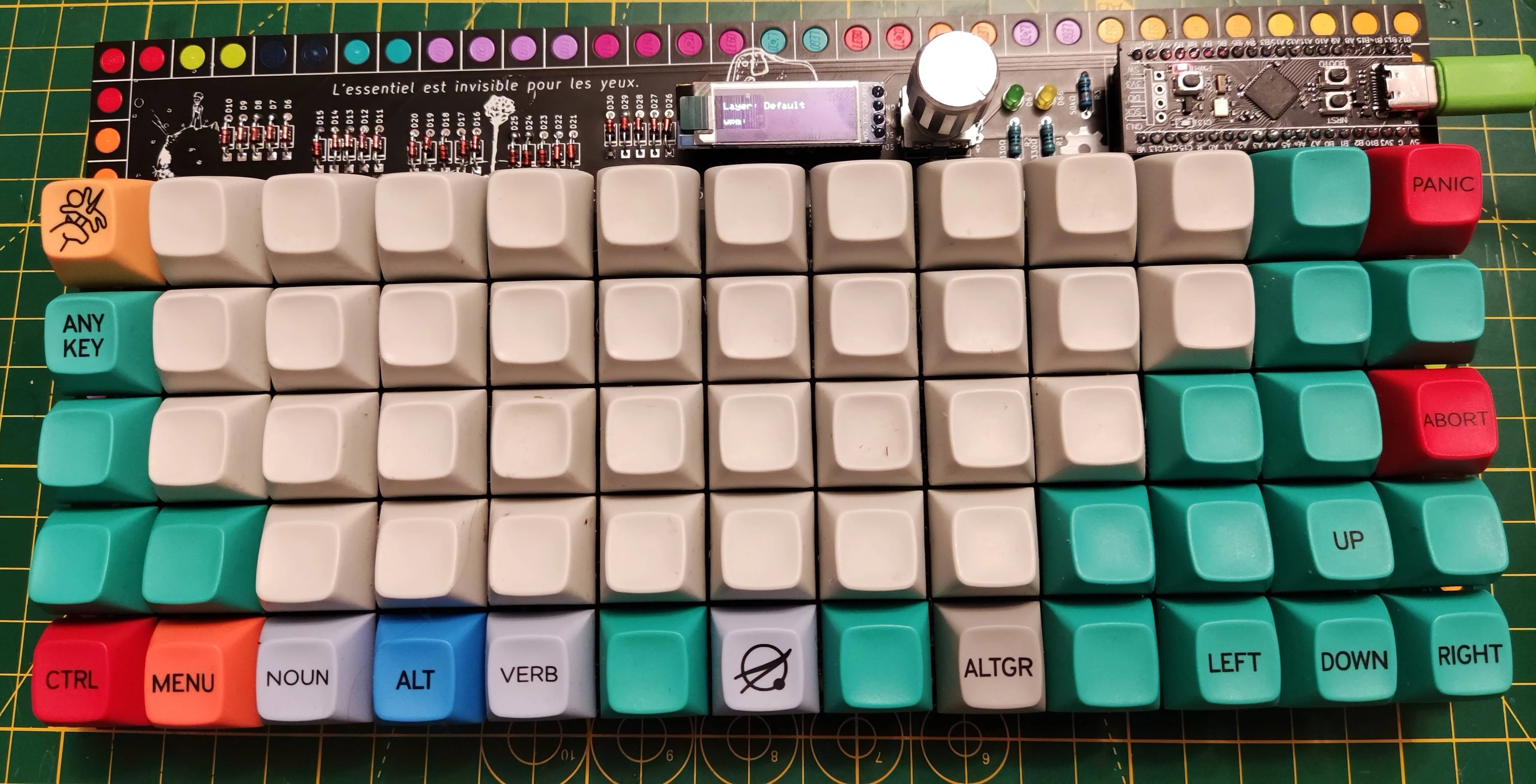
Step-by-Step Assembly Guide
Before You Start
Prerequisites
This guide assumes you know basic through-hole soldering, have reviewed the **BOM** section for your keyboard revision, and have all components and the PCB ready. While the soldering complexity is low, expect the full assembly to take around **2 hours**.Familiarize Yourself with the PCB
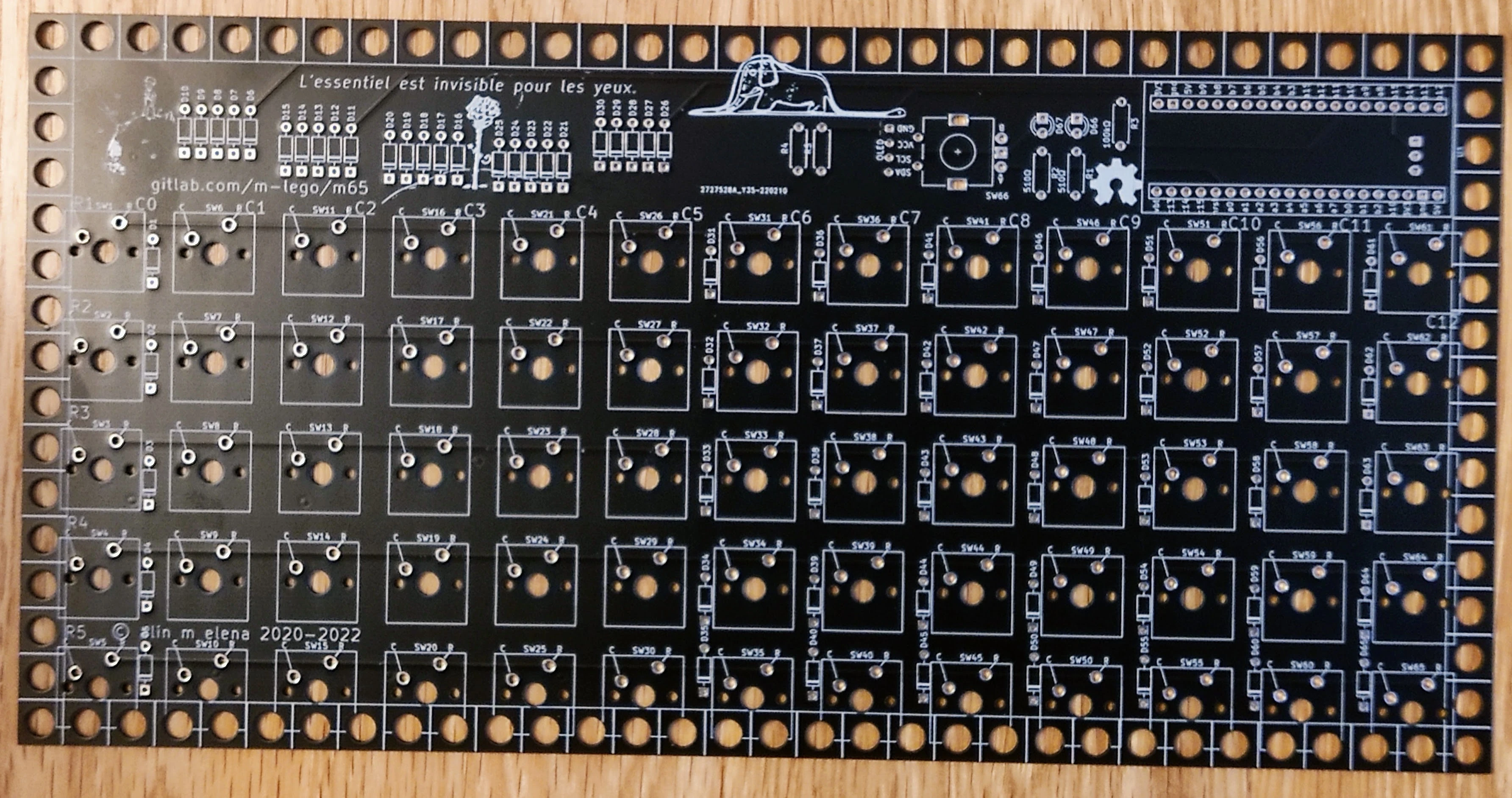
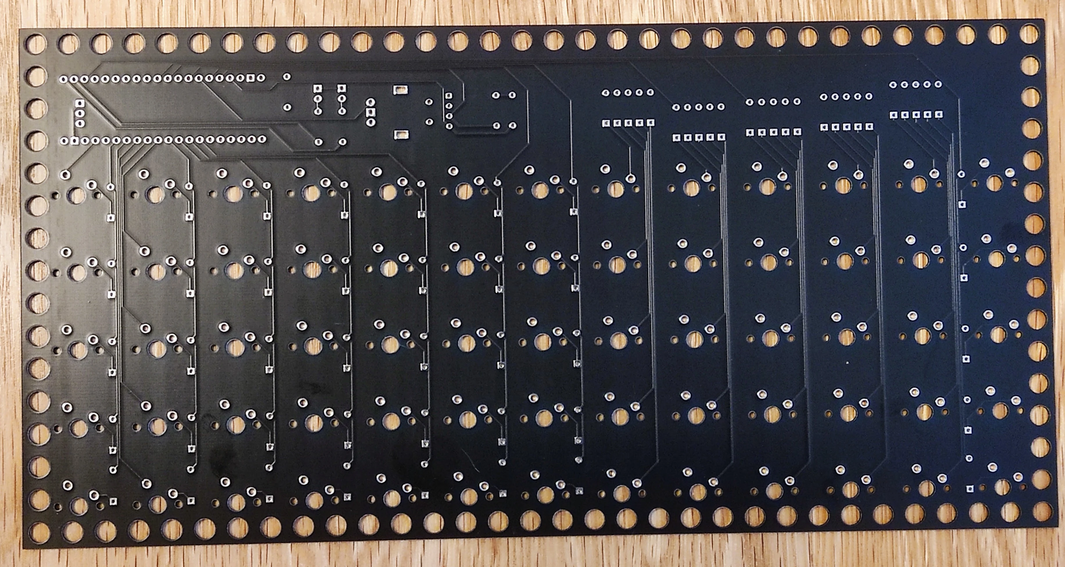
* **Front side**: The side with the silkscreen artwork (switches, MCU socket, and OLED mount on this side).
* **Back side**: The underside where component leads are soldered.
* You can ignore `R4` and `R5` on older revisions (`m65 Rev 4`), as they are only used in advanced configurations with special I²C pull-ups.
1. Preparing the MCU Socket & Headers
Always Socket Your Microcontroller
Whatever MCU board you use (`STM32` BlackPill, Raspberry Pi Pico `RP2040`, or Seeed Studio `XIAO`), **strongly consider socketing it** so it can be replaced or reused easily.
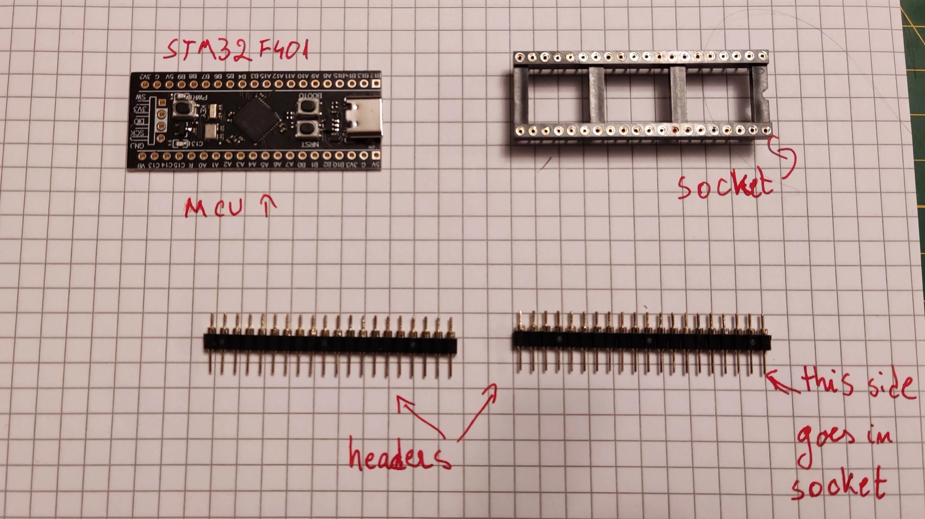
- For 40-pin boards, I use machined round pin headers paired with a 40-way DIL socket (or two single-row 20-pin female headers, which are especially convenient for Raspberry Pi Pico boards).
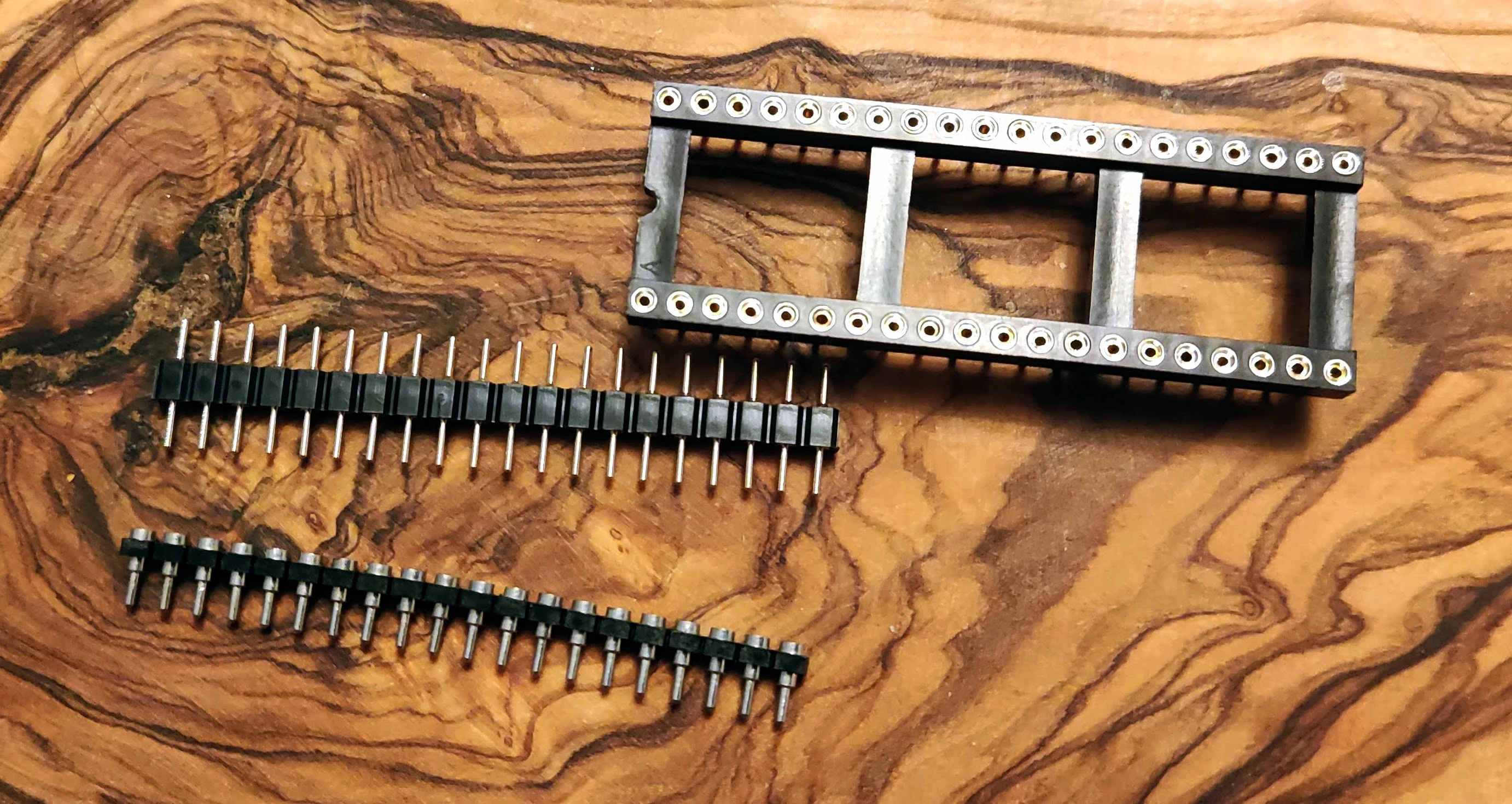
Header Orientation
Insert the male header pins partway into the socket with the **conical/tapered pins pointing down into the socket**, then place the MCU board on top. Using the socket as a jig keeps both rows perfectly parallel.
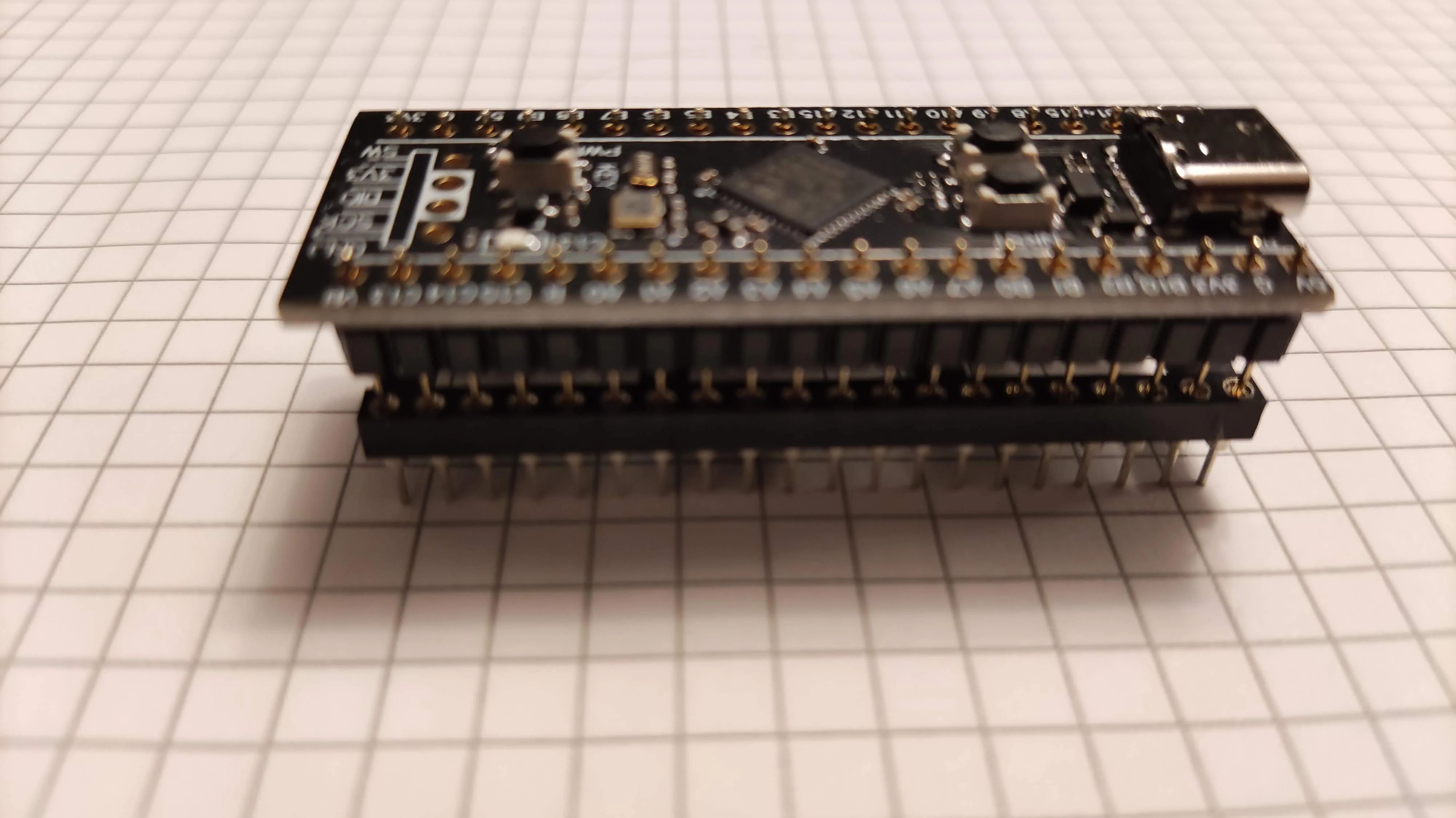
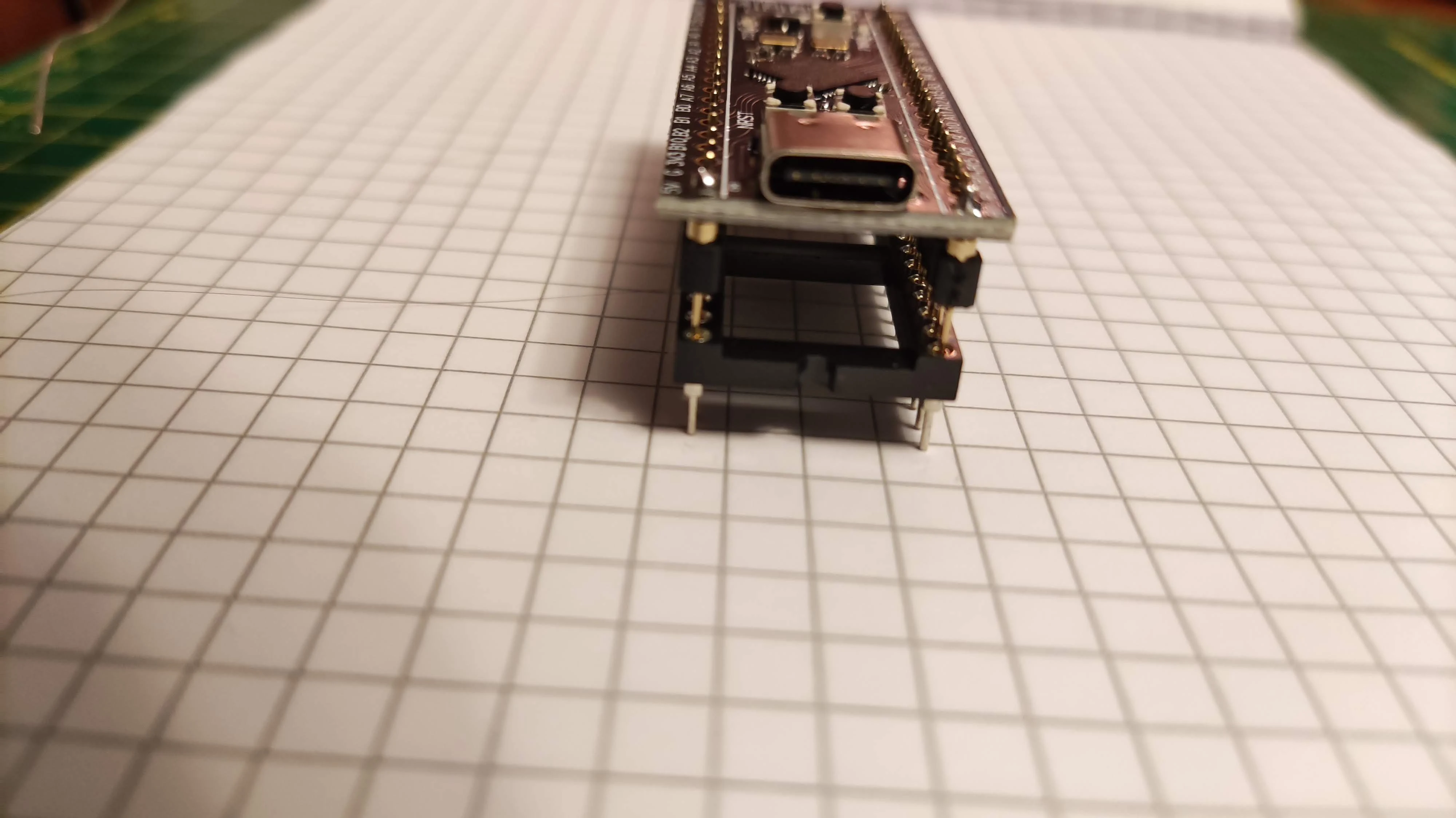
- Verify the headers are vertical and stable. Solder the two corner pins of each row first to tack the alignment, then solder the remaining pins.
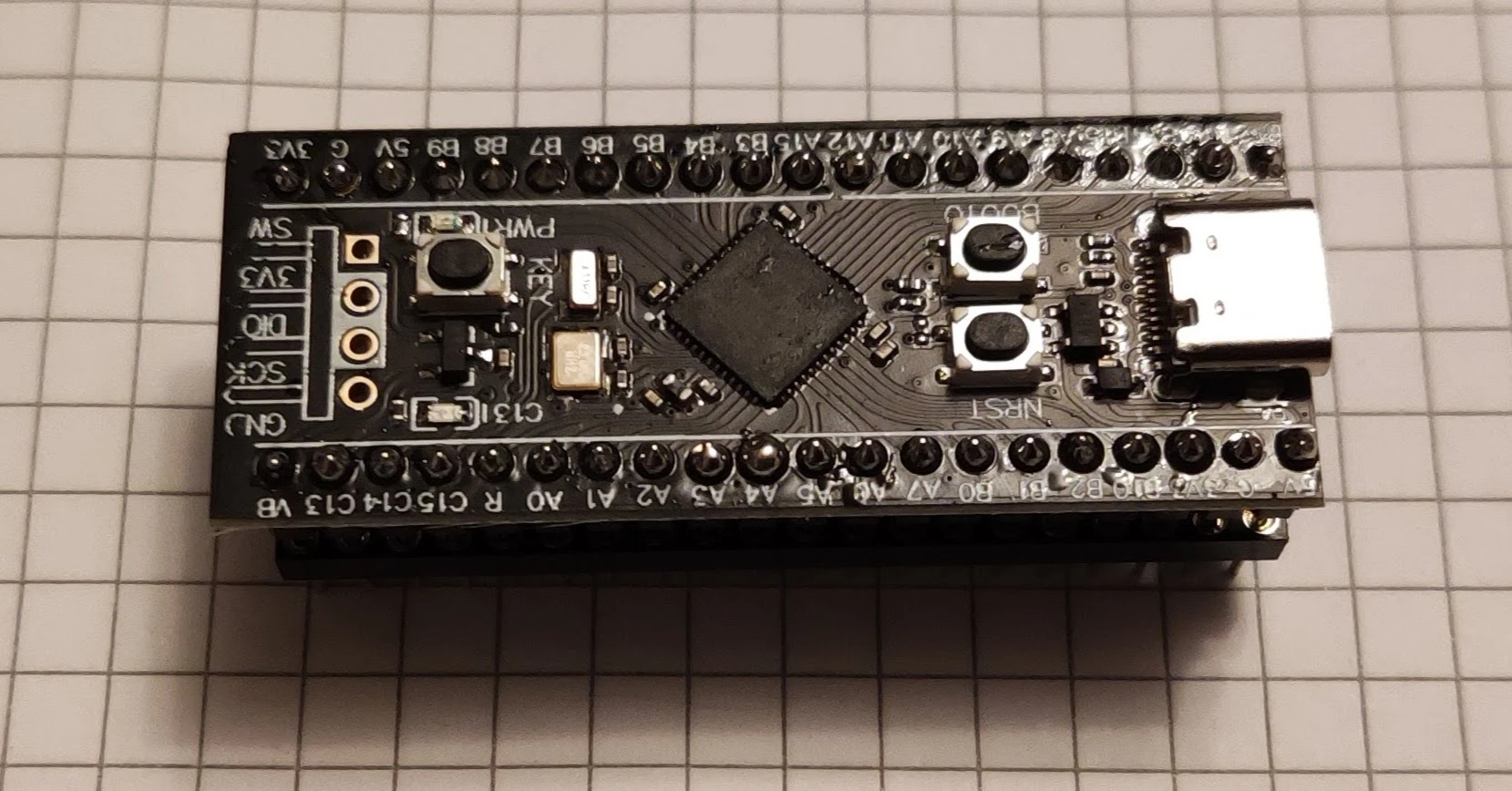

2. Preparing the OLED Display
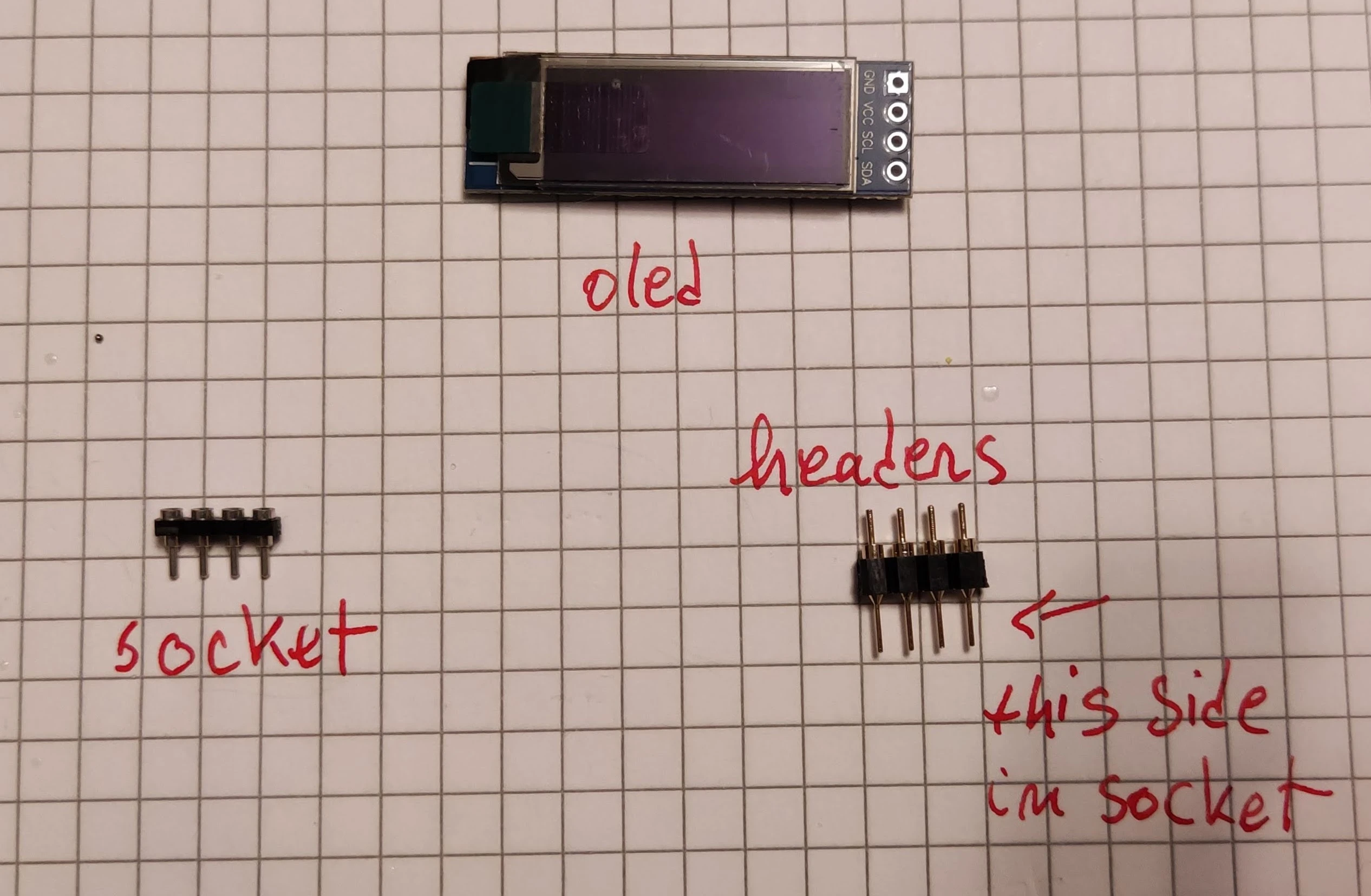
If your build includes an I²C OLED screen, socket it as well using a 4-pin row of round machine pins and a low-profile 1×4 socket:
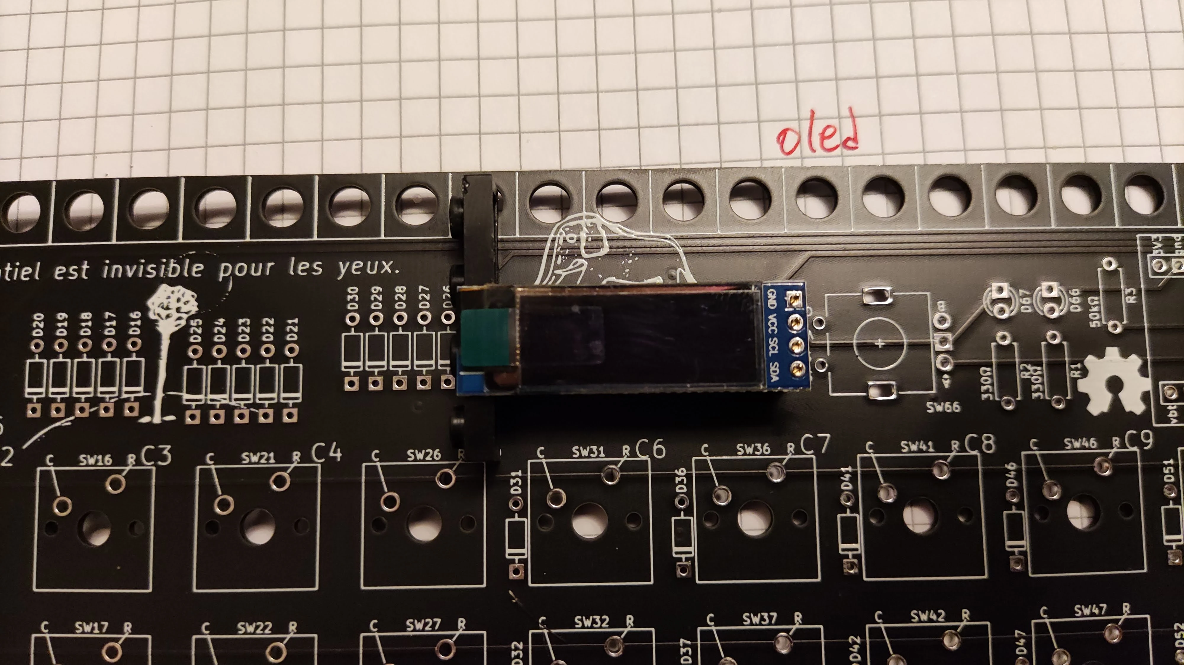
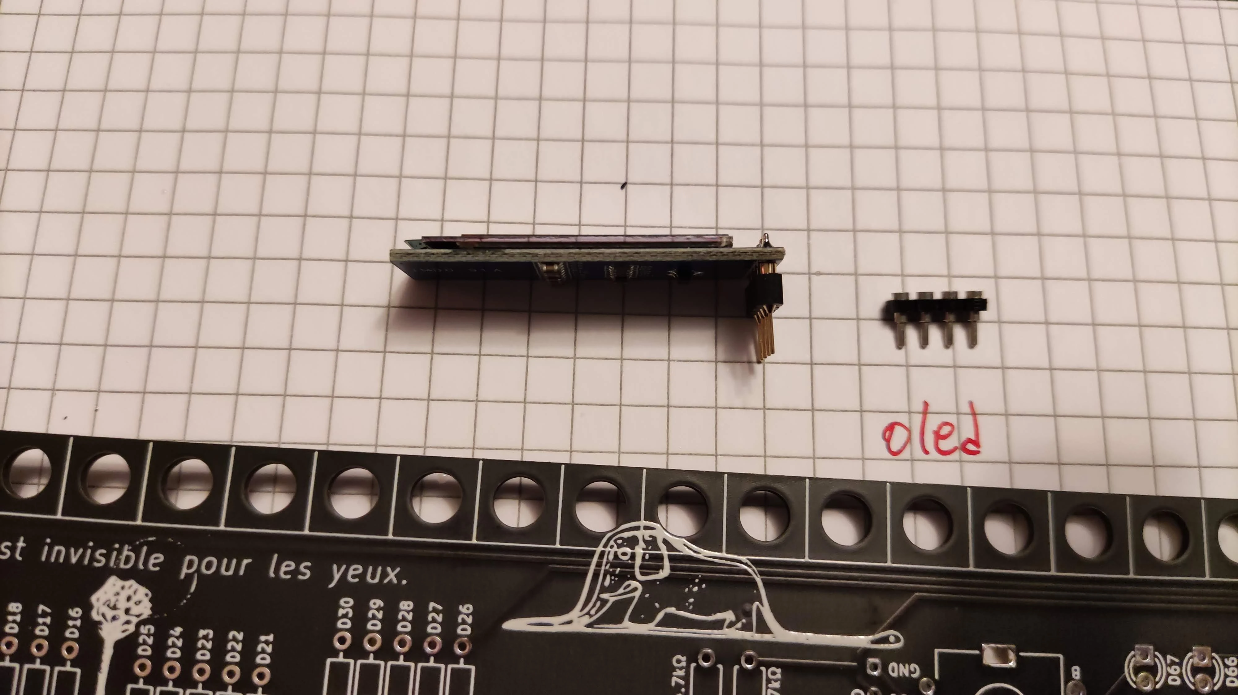
- Use the keyboard PCB itself as an alignment jig: place the 4-pin header into the PCB pads (conical side pointing down toward the PCB), seat the OLED module on top, and level it with a bit of Blu-Tack or painter's tape.
- Solder the 4 pins to the OLED module only (do not solder the header directly to the keyboard PCB!), then remove the OLED assembly.
3. Soldering the Diodes
Prepare your 1N4148 (DO-35 through-hole) signal diodes (65 or 66 for m65/m66, 60 for m60, 48 for m48, 20 for m20).
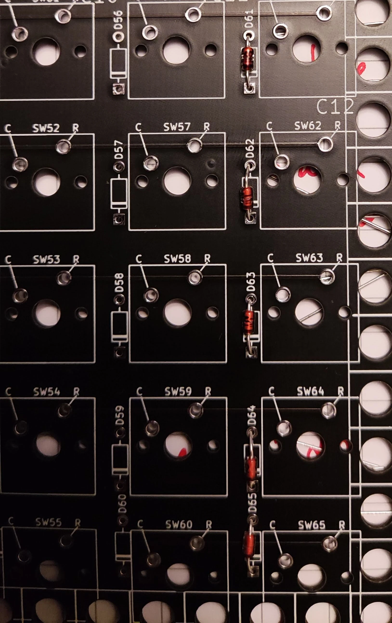
- Bend the leads at 90° as shown below.

Diode Polarity (Black Cathode Band)
Note the **black ring/collar (cathode)** at one end of the glass body. Insert every diode from the front of the PCB with the **black collar oriented toward the bottom/lower pad** (matching the silkscreen diode triangle/bar symbol).
- Splay the leads outward on the back of the PCB to hold each diode snug against the board while flipping it over. Working column by column is fastest.
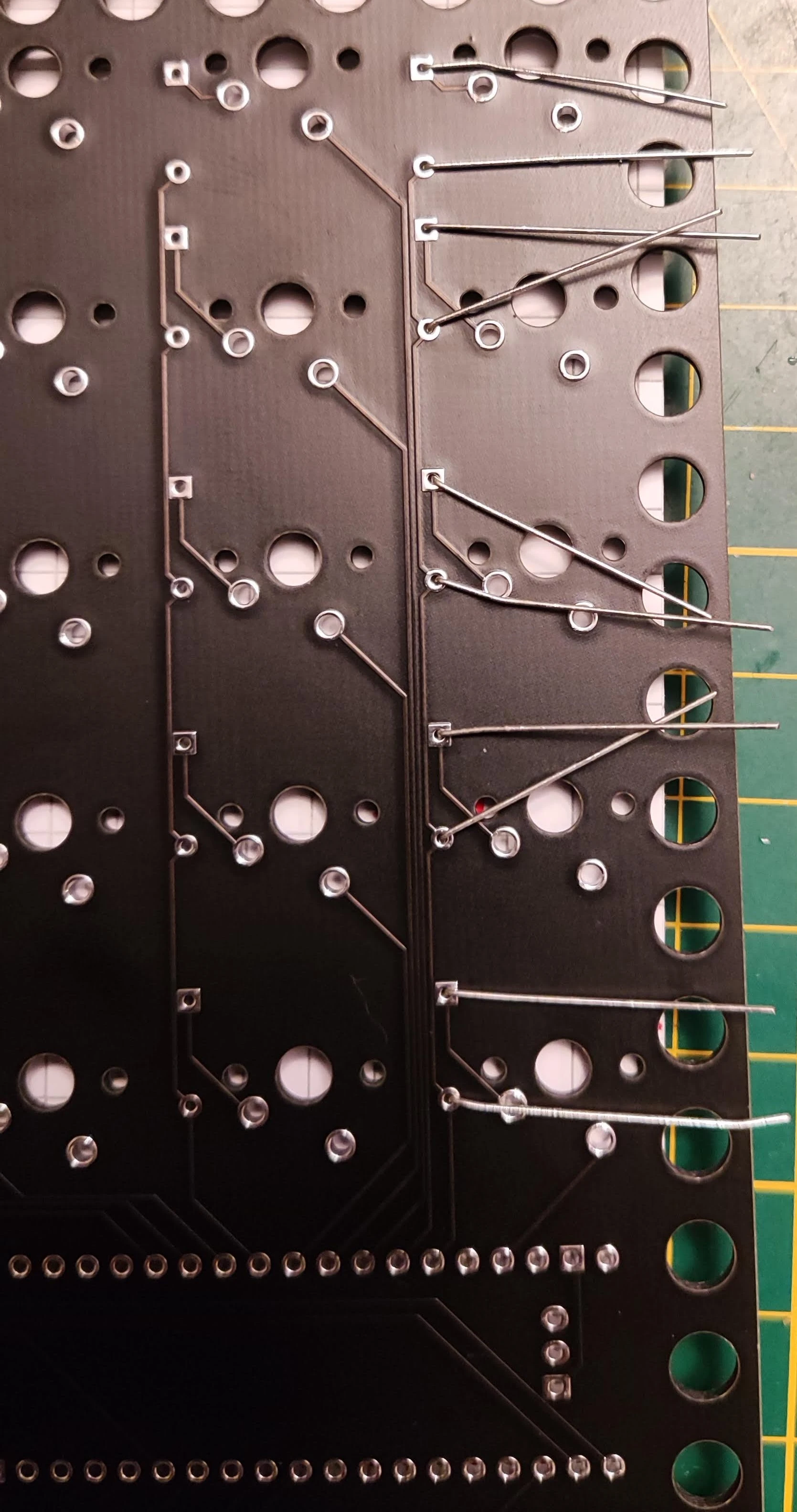
Trimming Diode Leads
After soldering, use flush cutters to trim the excess leads cleanly at the solder joint. *(Alternatively, you can wiggle the leads until they snap off at the joint, though it is good practice to briefly reflow the joint afterward if you do so.)*
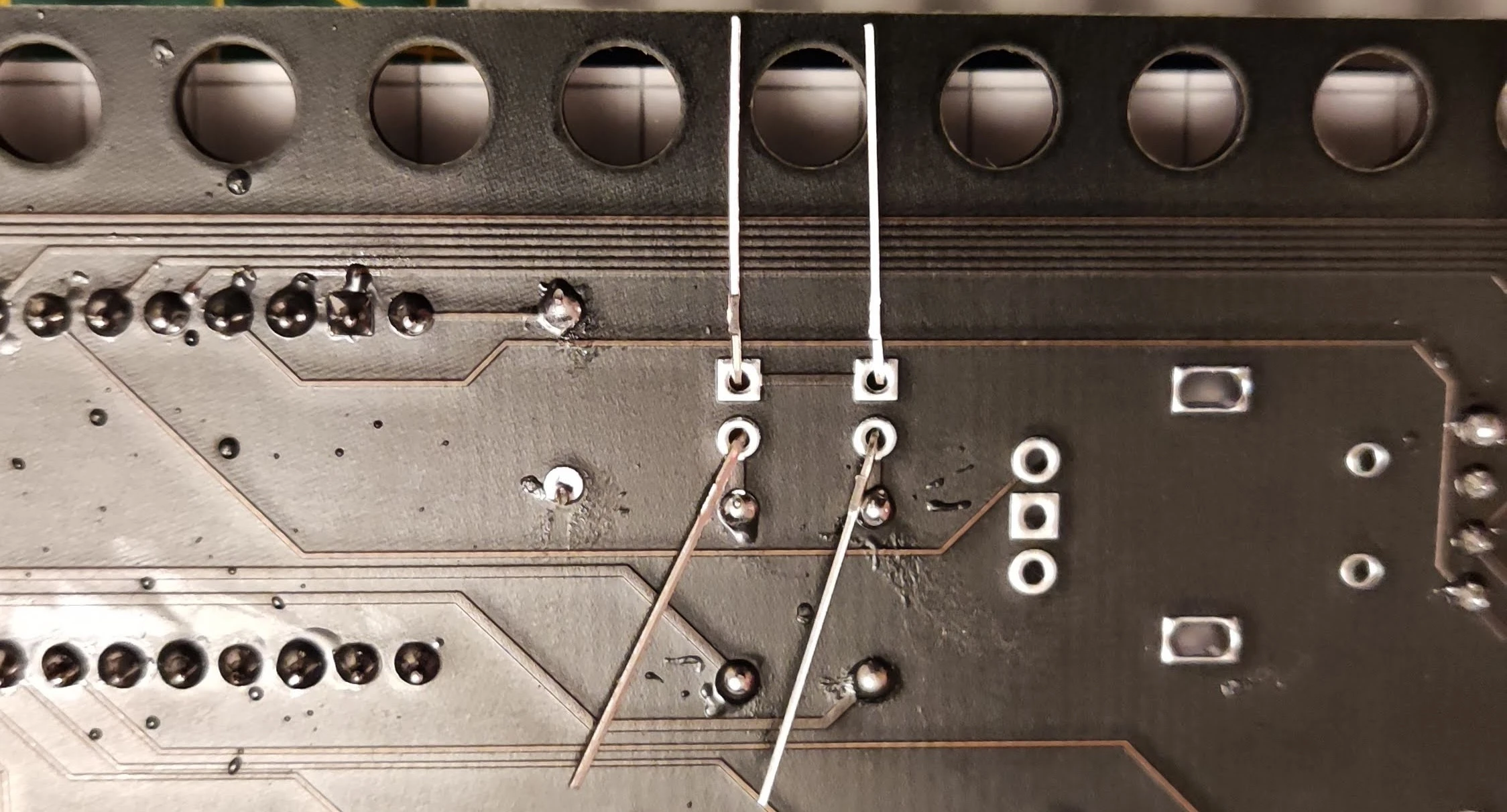
- For the horizontal diodes along the top row, bend one lead straight down beside the glass body as shown below so you can populate the entire row in one pass:
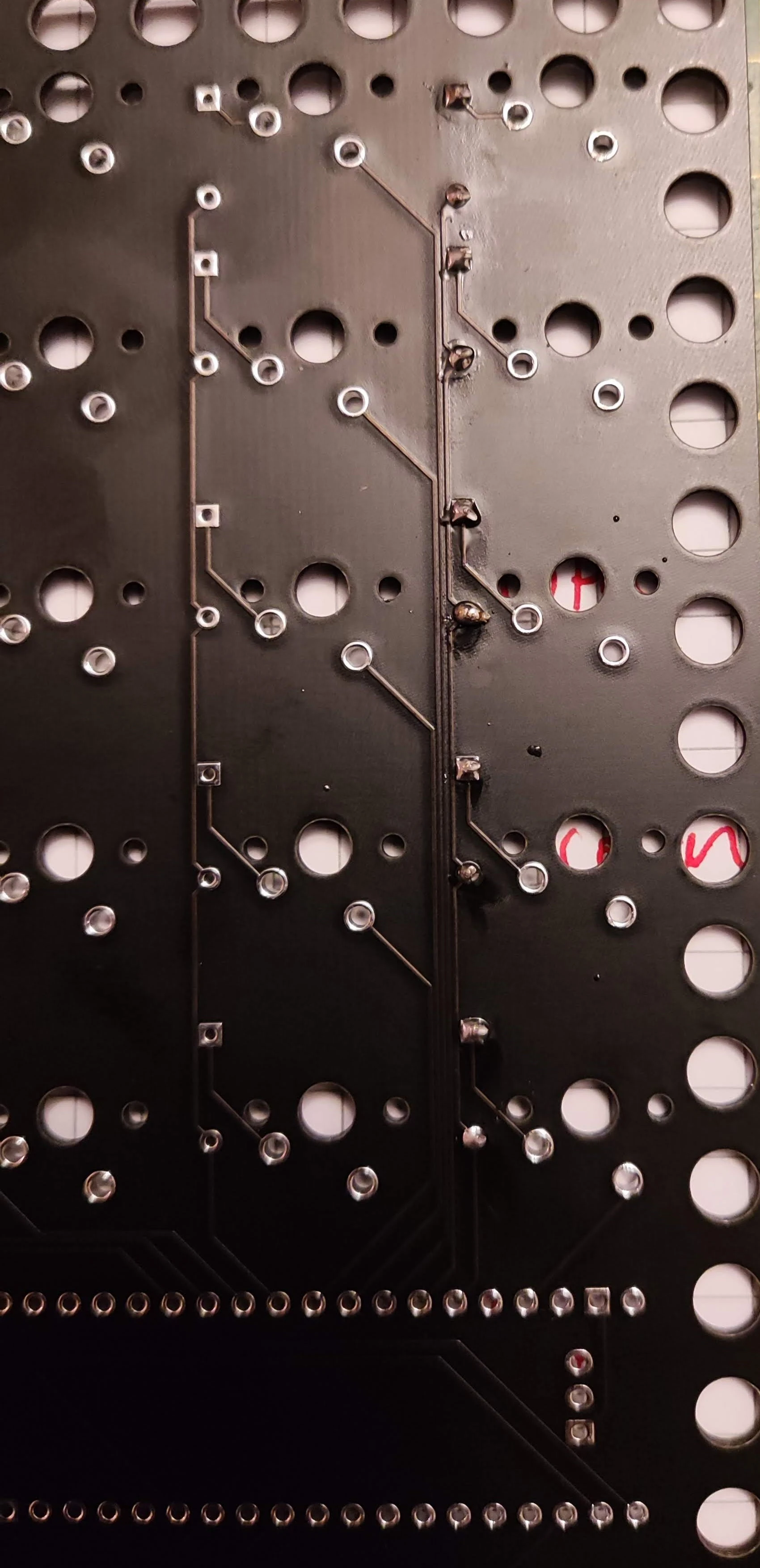
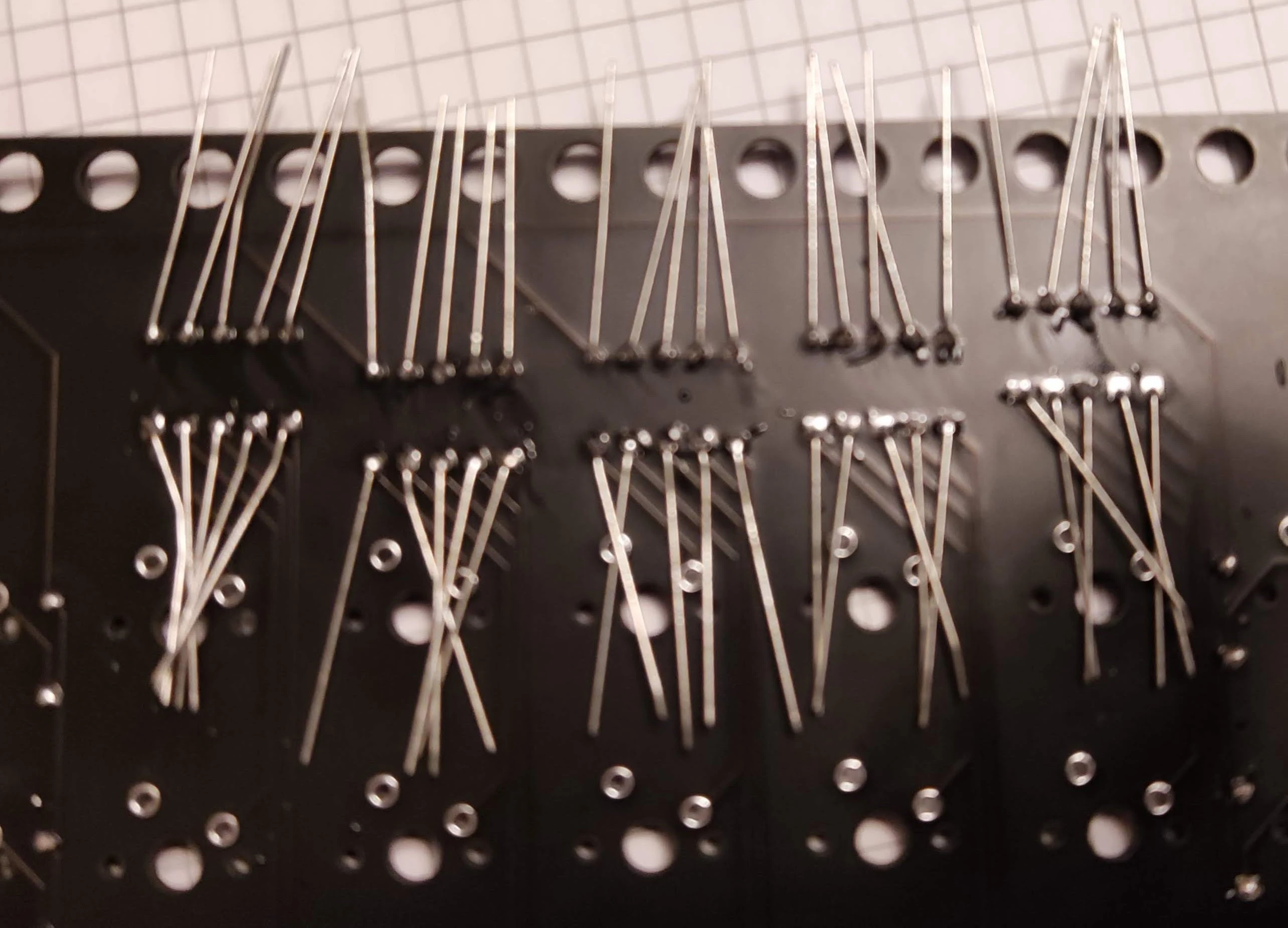
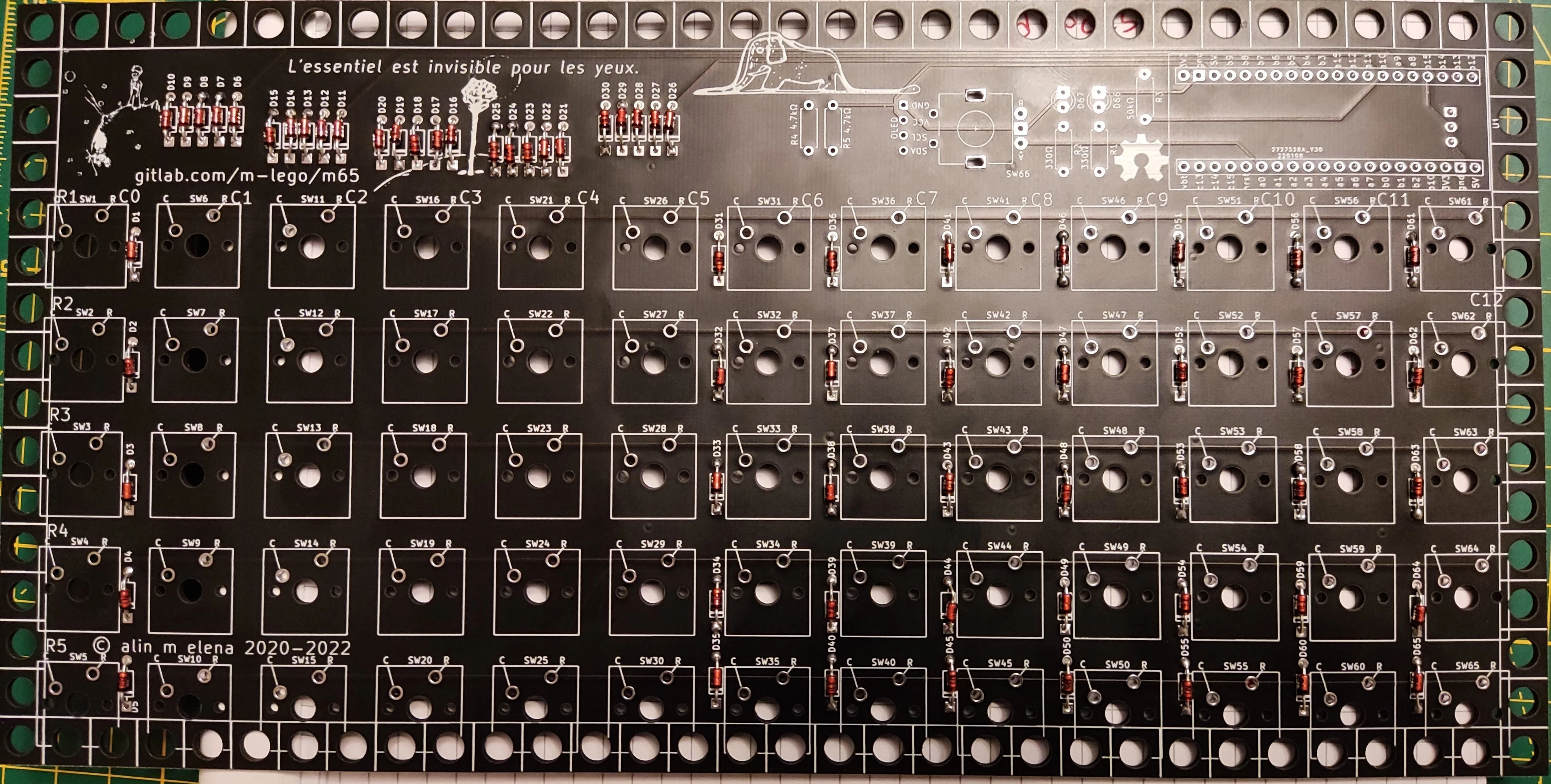
4. Soldering the Resistors
Resistors are non-polarized — bend, insert, and splay the leads just like the diodes, ensuring the right resistance value goes into each footprint:
Resistor Values (Rev 4–6)
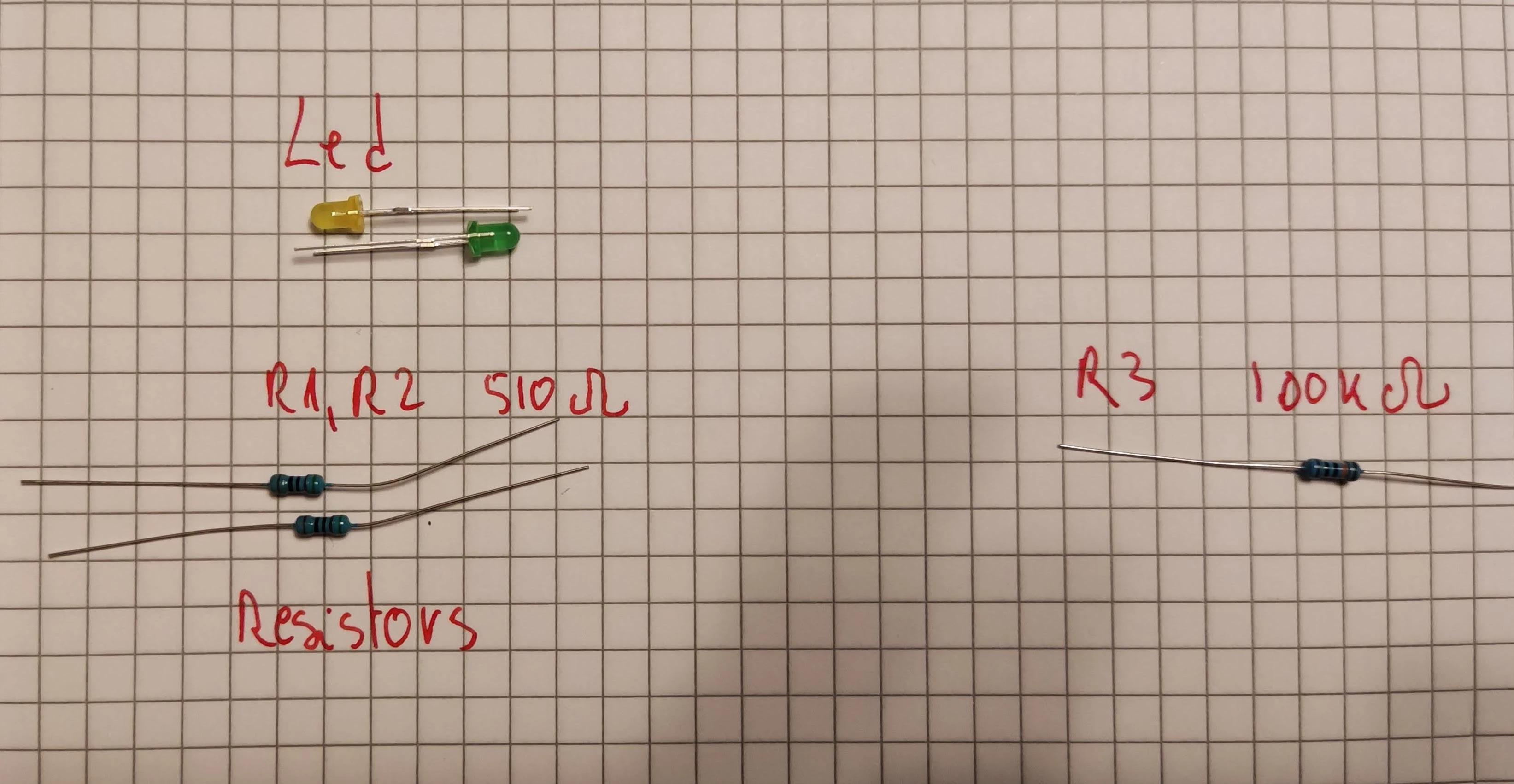
* **`R3` (100 kΩ or 22 kΩ)**: Required on `STM32F401`/`F411` BlackPill builds so the MCU enters DFU bootloader mode reliably.
* **`R1` & `R2` (LED Current-Limiting)**: Select based on your LED color and desired brightness — 510 Ω gives a pleasant glow on green/yellow LEDs, while 1 kΩ works well for bright white LEDs.
Testing LED Brightness & Polarity
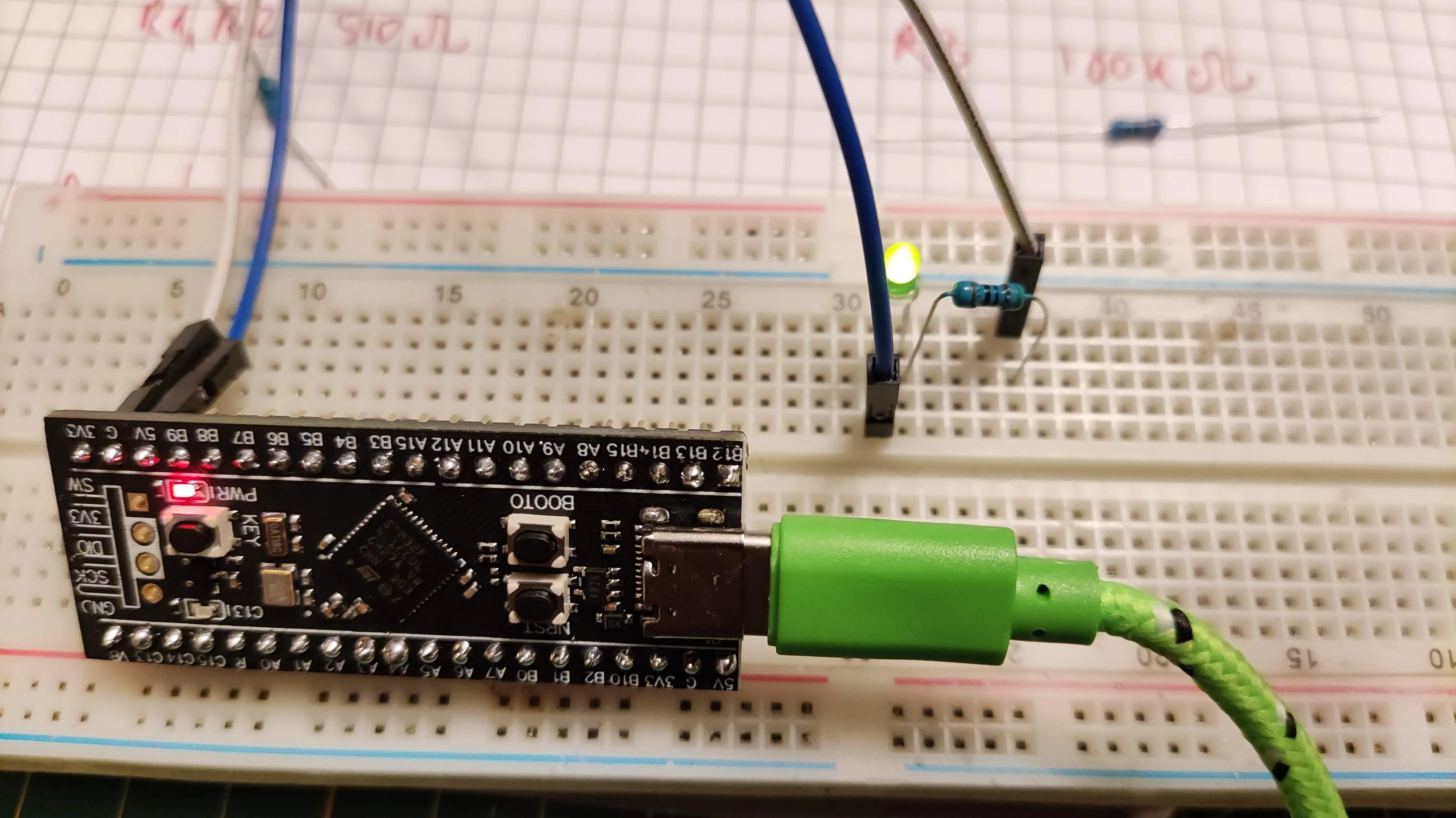
Before soldering `R1`/`R2` and the LEDs, test them on a breadboard (or with DuPont jumper wires from a 3.3 V pin on your MCU) to confirm you like the brightness and to verify which LED leg is positive (3.3 V) and which is negative (`GND`) — some batch LEDs do not follow the standard long-leg-anode convention!
5. Soldering the MCU & OLED Sockets
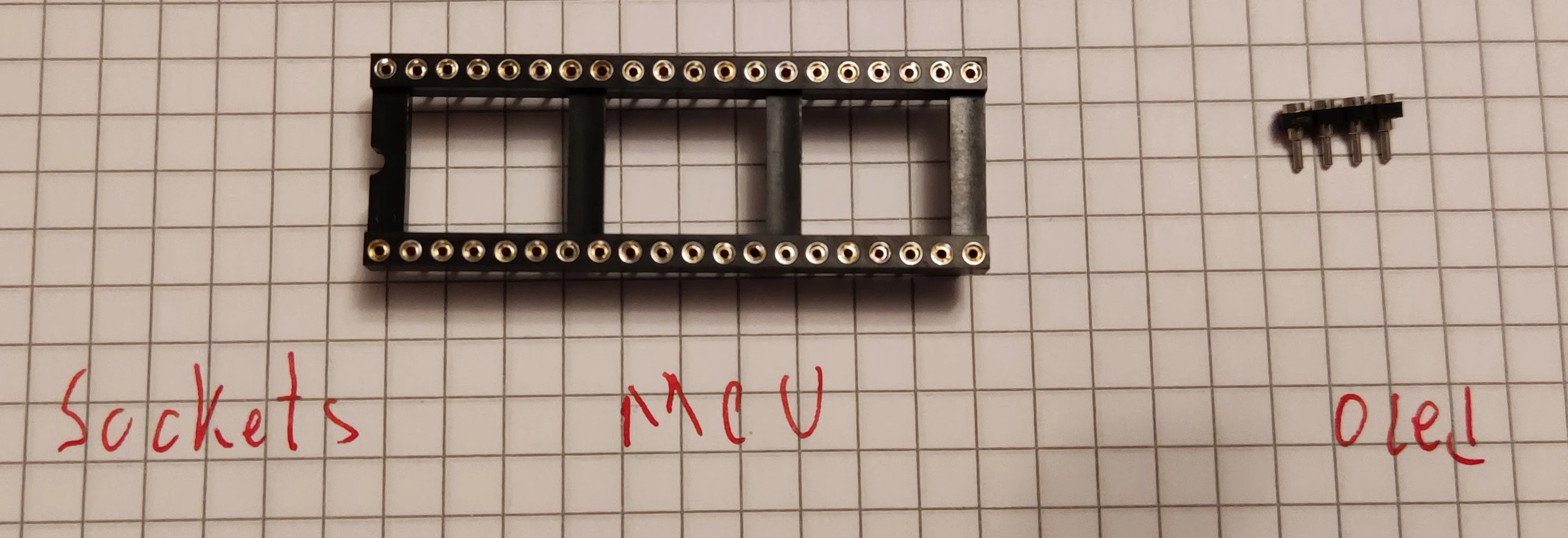
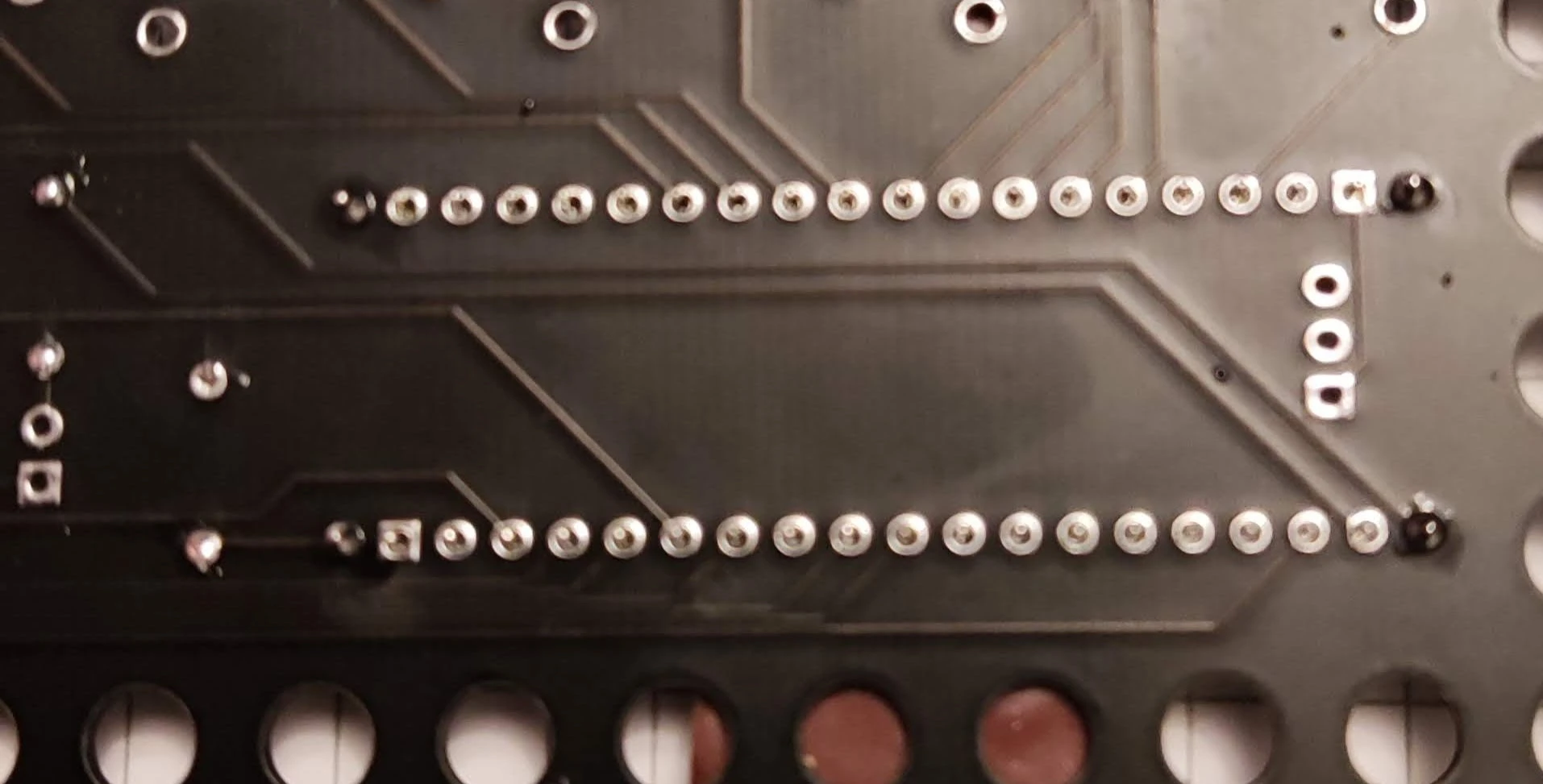
- Place the 40-way DIL MCU socket (or female headers) onto the front of the PCB and hold it flat with painter's tape.
- Flip the board over, solder the diagonal corner pins first while pressing the socket flush against the PCB, verify alignment, and solder all remaining pins.
- Repeat for the 4-pin OLED socket.

6. Soldering Indicator LEDs
LED Polarity
Insert each LED into the position matching its resistor (`R1` or `R2`). Ensure the **cathode (ground) leg goes into the square-plated hole**. Splay the legs, solder from the back, and trim flush.

7. Mounting & Soldering Switches
- Inspect your 5-pin switches to make sure no metal pins are bent, then press them firmly into the PCB until the plastic legs snap flush.
- Sight down each row and column to confirm all switches sit level and straight.
Loose-Fitting Switches
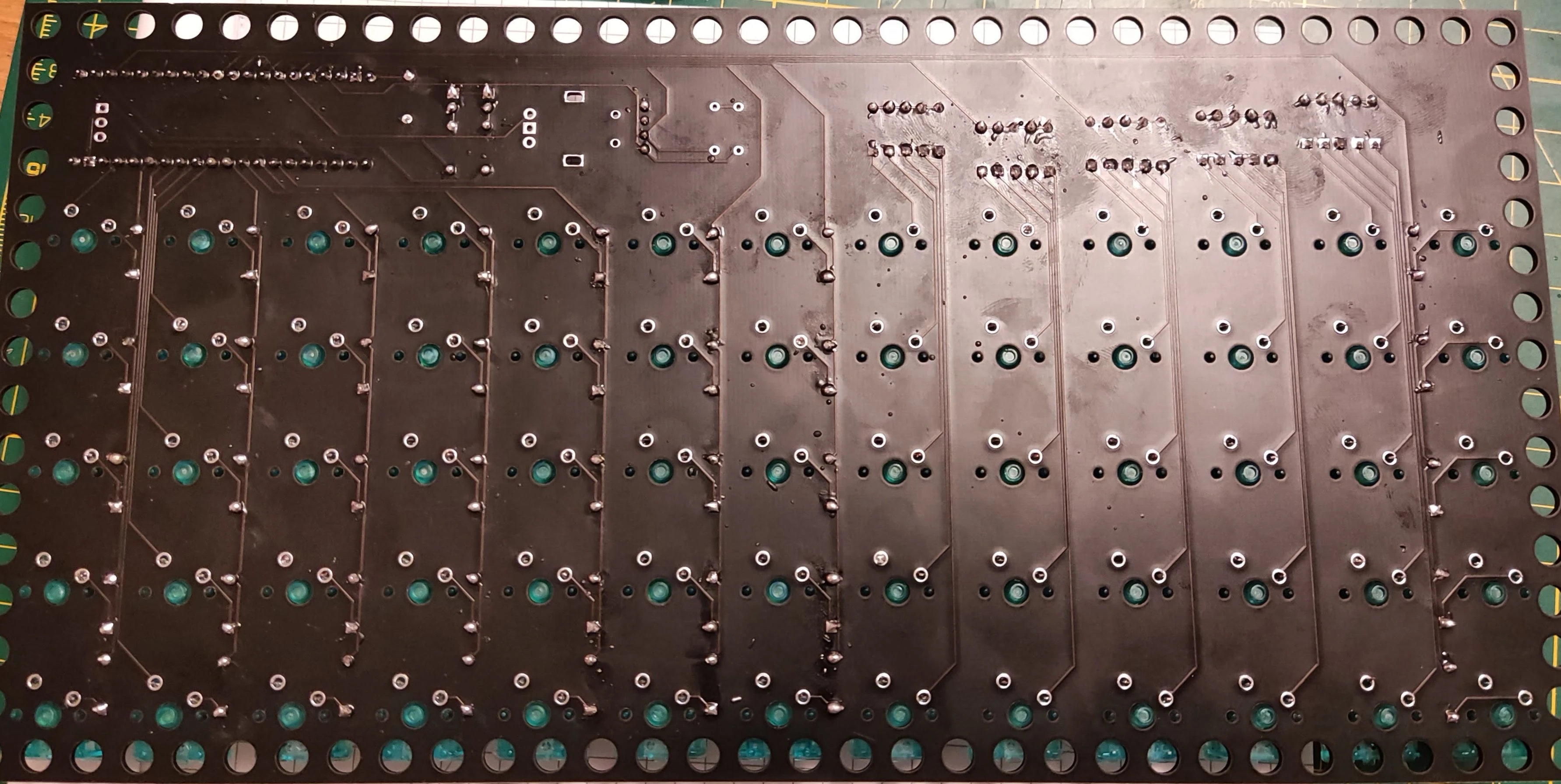
Some switch housings (such as certain Kailh batches) fit slightly looser in PCB-mount holes. Place a flat hardcover book on top of the switches when flipping the board over so every switch stays seated flush against the PCB while soldering.

8. Soldering the Rotary Encoder
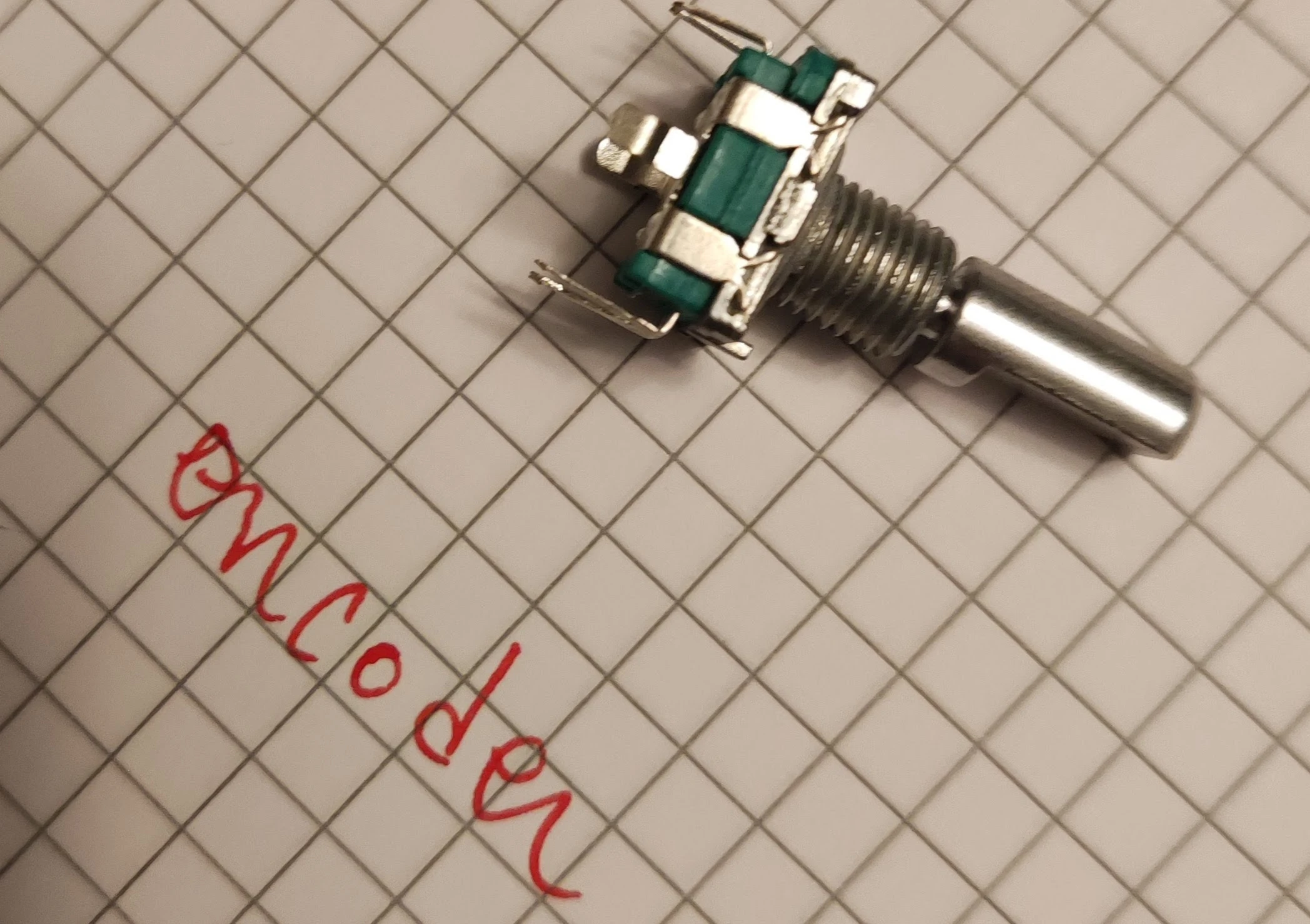
Snap the EC11 rotary encoder into its footprint at the top-right corner. On earlier revisions (Rev 1–8), only the 3 rotational pins are routed; on Rev 9+ and m66, all 5 signal pins (including the push-button switch) are active. Solder all signal pins as well as the two side mounting tabs for mechanical strength.
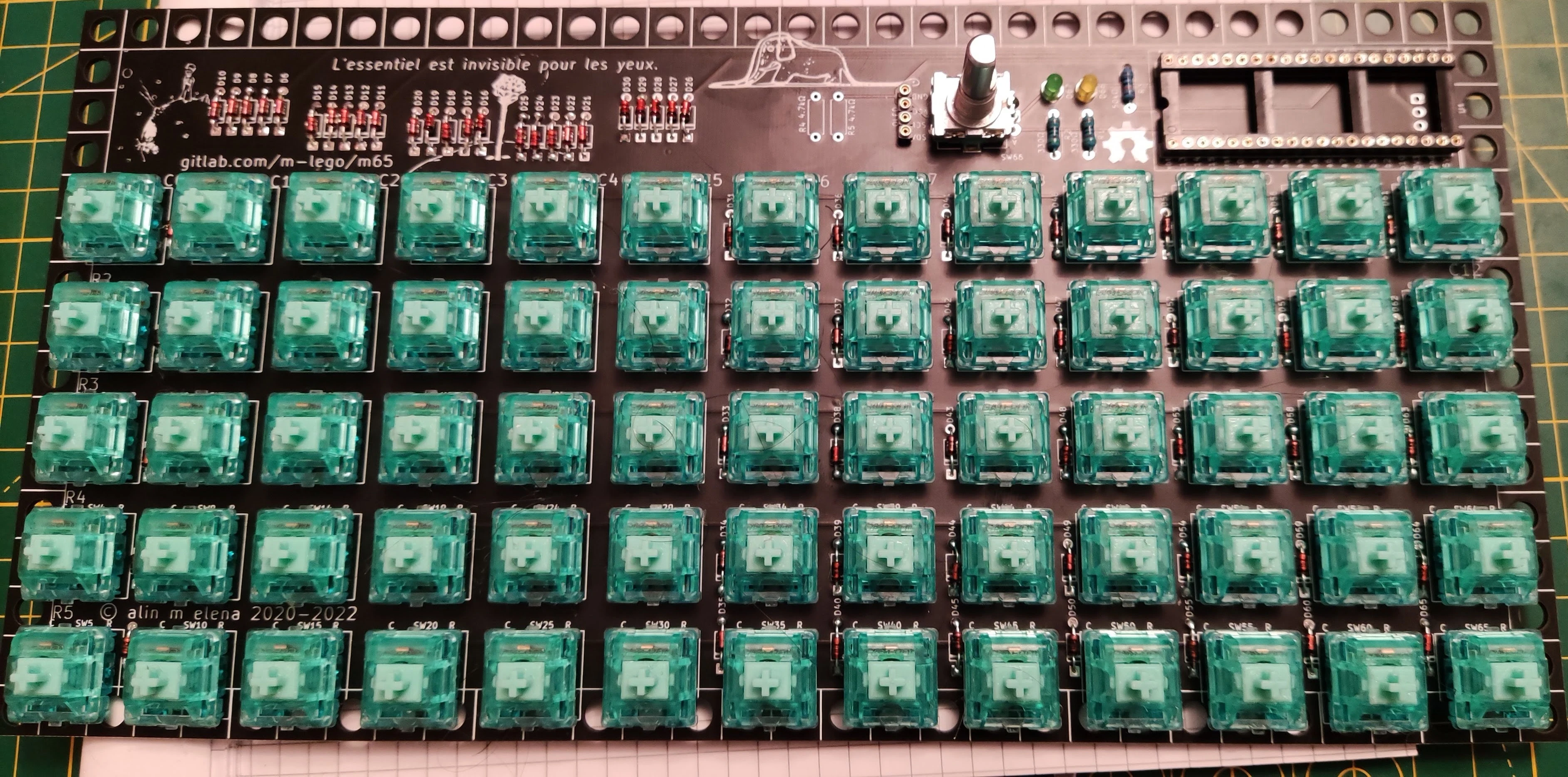
PCB Soldering Complete!
Your keyboard PCB assembly is now electrically complete.
9. Building the LEGO Enclosure & Final Testing
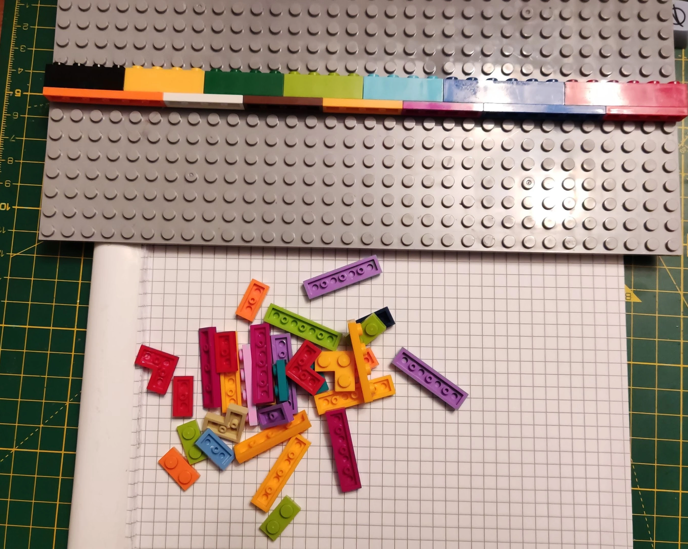
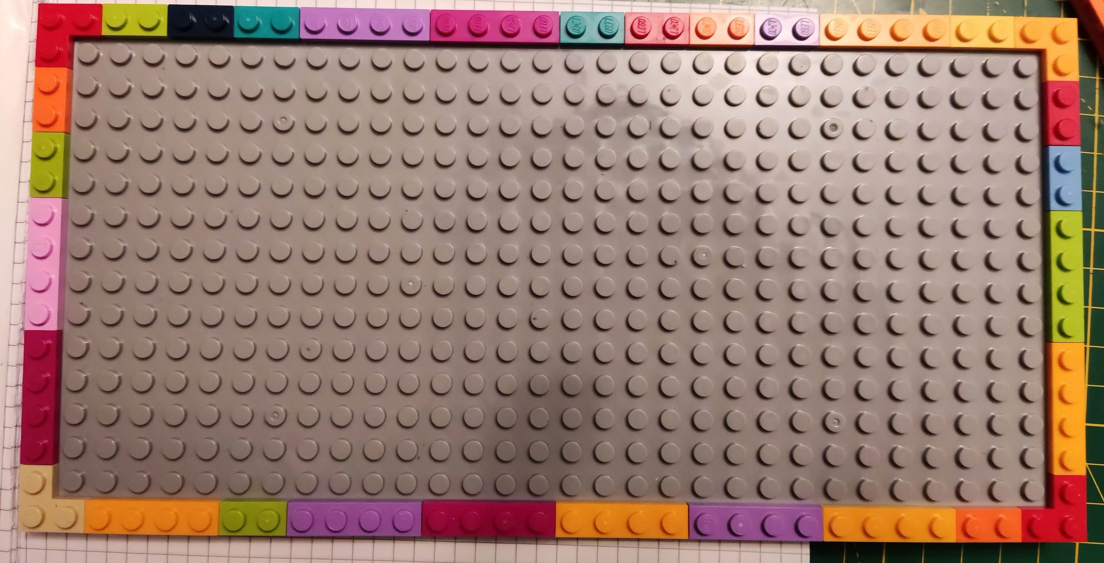
- Assemble your LEGO base using a 16×32 baseplate (or two 16×16 plates) and perimeter 1×2 / 1×4 plates. For a ~6° typing angle, stack a full brick + plate along the top edge.
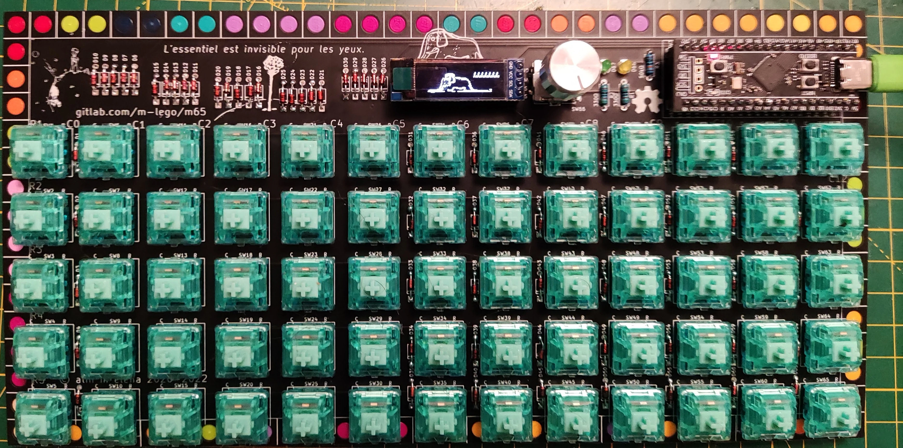
- Add a sheet of hobbycraft foam inside the cavity for sound dampening, then align the PCB mounting holes over the perimeter LEGO studs and press down gently until the 1.6 mm PCB sits flush with the studs.
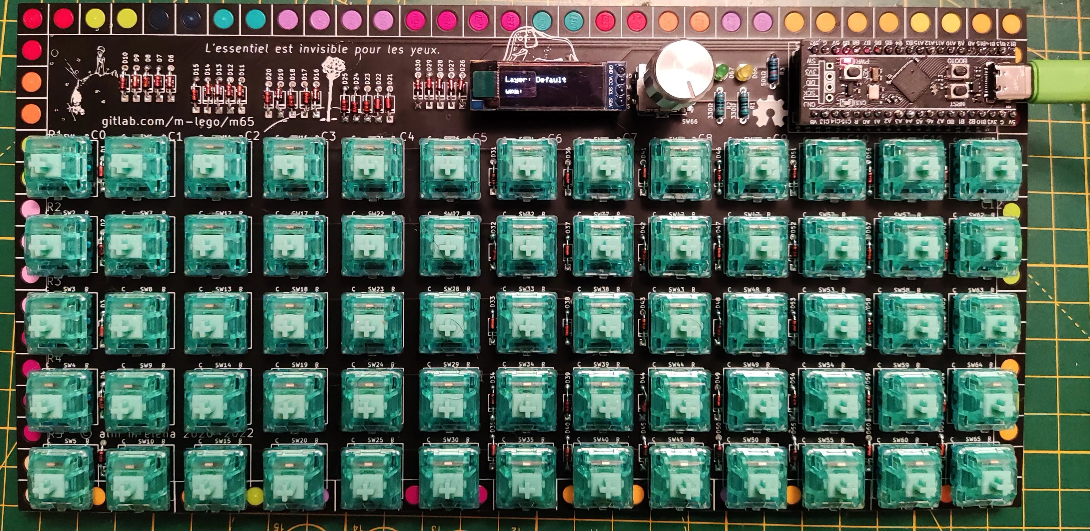
- Seat the socketed MCU, OLED screen, and encoder knob, then plug in the USB cable.
First Power-On Checklist
* **OLED Screen**: Displays "an elephant inside a boa constrictor" splash graphic for a few seconds, then switches to the active layer indicator and live WPM counter.
* **Rotary Encoder**: Turning the knob adjusts system volume (`Vol+` / `Vol-`).
* **Layer Tap-Dance LEDs**:
    * Double-tap the **3rd key from the left on the bottom row** (`Lower`): the first indicator LED next to the encoder lights up (double-tap again to toggle off).
    * Double-tap the **5th key from the left on the bottom row** (`Raise`): the second indicator LED lights up.
* **Key Matrix**: Test every switch in a keyboard tester — then install your keycaps and enjoy!