How a Keyboard Matrix Works — Practical 3×3 Guide
Setting Up the Scene
If you have read the official QMK guides — How a Keyboard Matrix Works, How Keyboards Work, and Understanding QMK's Code — and want a concrete, end-to-end example connecting the schematic, diode orientation, QMK firmware, and PCB layout, this guide walks through a complete 3×3 mechanical keypad (m3x3) using a WeAct STM32F401 BlackPill (and Raspberry Pi Pico RP2040).
MCU Pin Quirks
Every microcontroller family has its own pin constraints and boot strapping requirements. Always check which pins are reserved or require pull-ups before finalizing a PCB:
* [WeAct BlackPill `STM32F401CCU6` Pinout](https://stm32-base.org/boards/STM32F401CCU6-WeAct-Black-Pill-V1.2.html) & [`STM32F411CEU6` Pinout](https://stm32-base.org/boards/STM32F411CEU6-WeAct-Black-Pill-V2.0.html)
* [QMK WeAct BlackPill `STM32F4x1` Platform Notes](https://docs.qmk.fm/#/platformdev_blackpill_f4x1?id=weact-blackpill-stm32f4x1)
Diode Orientation: COL2ROW vs. ROW2COL
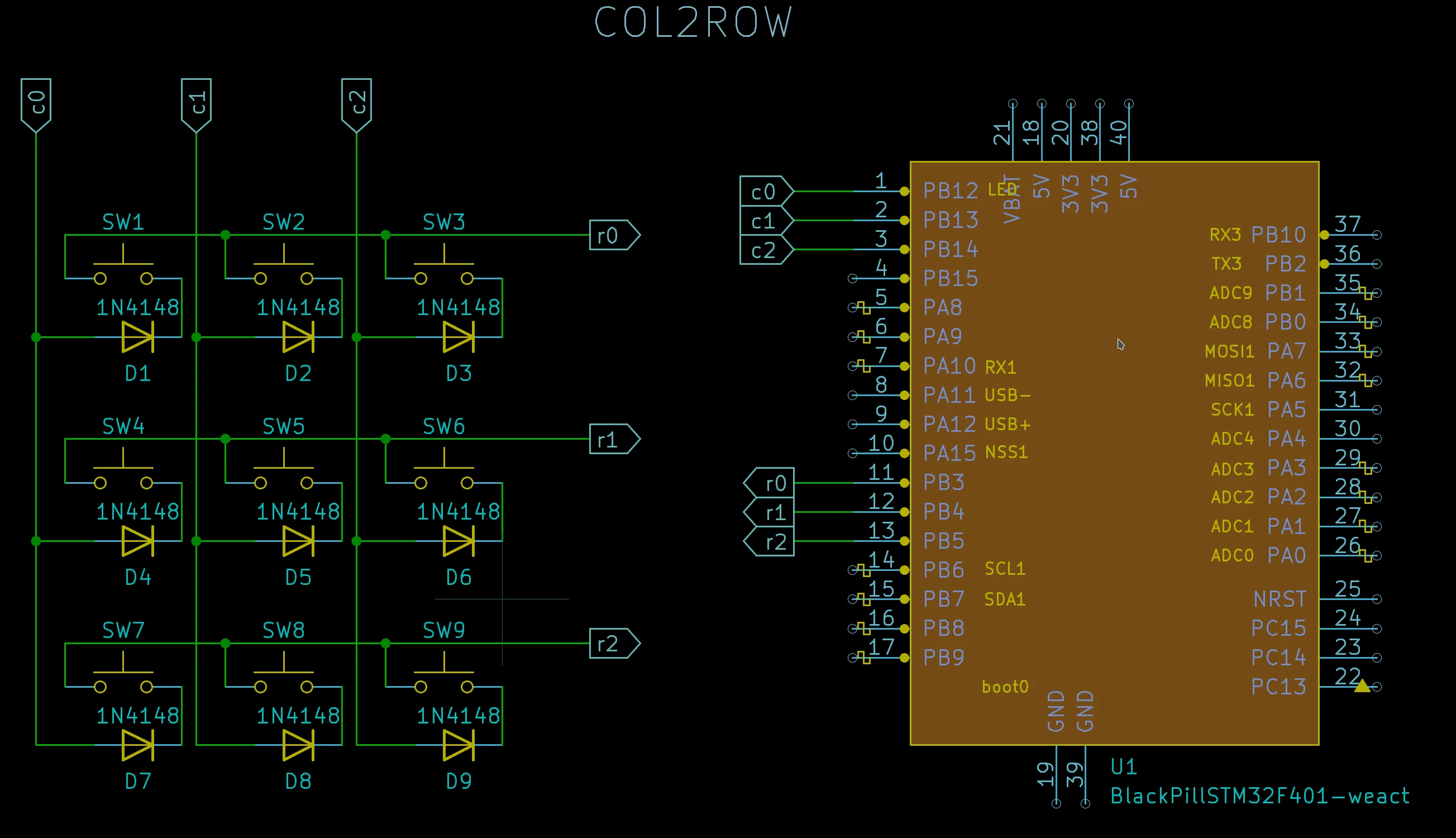
Adding a 1N4148 signal diode in series with each key switch prevents ghosting when multiple keys are pressed simultaneously. Because a diode conducts current in only one direction, there are two valid ways to orient the diodes across your matrix intersections:
COL2ROW (Column → Row) |
ROW2COL (Row → Column) |
|---|---|
 |
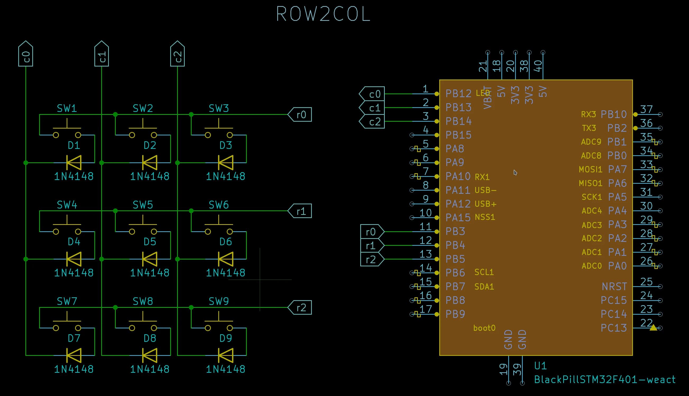 |
| Diode cathode (black band) points toward the Row line | Diode cathode (black band) points toward the Column line |
In both circuits above, Rows (R0–R2) connect to B3, B4, B5 and Columns (C0–C2) connect to B12, B13, B14. The only hardware difference is the direction of the diode!
In QMK's config.h (or info.json), this is configured via DIODE_DIRECTION:
Left Circuit (`COL2ROW`)
// config.h
#define DIODE_DIRECTION COL2ROW
// info.json
"diode_direction": "COL2ROW"
Right Circuit (`ROW2COL`)
// config.h
#define DIODE_DIRECTION ROW2COL
// info.json
"diode_direction": "ROW2COL"
At this stage, you already have everything needed to write and test the firmware on a breadboard using only the MCU and a few DuPont jumper wires!
Creating a Simple QMK Firmware
Once you have set up your QMK environment, QMK's CLI can scaffold the entire keyboard definition automatically.
Design Parameters for
m3x3* **MCU Type**: `blackpill_f401` (or `blackpill_f411`) * **Column Pins (`C0–C2`)**: `B12`, `B13`, `B14` *(order matters!)* * **Row Pins (`R0–R2`)**: `B3`, `B4`, `B5` *(order matters!)* * **Diode Direction**: `COL2ROW` * **Keyboard Name**: `m3x3` * **GitHub Username / Author**: `alinelena` / `"dr faustroll"`
Scaffold the Keyboard
qmk new-keyboard -n "dr faustroll" -u alinelena -t blackpill_f401 -kb m3x3 -l ortho_3x3
QMK generates the following directory structure inside keyboards/m3x3/:
Ψ Generating a new QMK keyboard directory
Ψ Created a new keyboard called m3x3.
Ψ To start working on things, `cd` into keyboards/m3x3,
Ψ or open the directory in your preferred text editor.
Ψ And build with qmk compile -kb m3x3 -km default.

keyboards/m3x3/
├── config.h
├── info.json
├── keymaps/
│   └── default/
│       └── keymap.c
├── readme.md
└── rules.mk
Configure info.json and keymap.c
-
Set Diode Direction (
keyboards/m3x3/info.json):json "diode_direction": "COL2ROW", -
Set Matrix Pins (
keyboards/m3x3/info.json): Replace the placeholder pins with our actual row and column pins:json "matrix_pins": { "cols": ["B12", "B13", "B14"], "rows": ["B3", "B4", "B5"] }, -
Customize the Keymap (
keyboards/m3x3/keymaps/default/keymap.c): See QMK's Basic Keycodes reference. Replace the defaultKC_A–KC_Iblock with a 1–9 numpad layout:c [0] = LAYOUT_ortho_3x3( KC_7, KC_8, KC_9, KC_4, KC_5, KC_6, KC_1, KC_2, KC_3 ) -
Compile & Flash:
bash
qmk compile -kb m3x3 -km default
qmk flash -kb m3x3 -km default
text Linking: .build/m3x3_default.elf [OK] Creating binary load file for flashing: .build/m3x3_default.bin [OK] Size after: text data bss dec hex filename 0 23032 0 23032 59f8 m3x3_default.bin
What If My Layout Is Not Listed in qmk new-keyboard?
If your exact matrix dimensions aren't listed as a community layout preset, simply bootstrap with the closest larger preset (for example, ortho_4x4) and trim keyboards/m3x3/info.json and keymaps/default/keymap.c:
- Update
"diode_direction"and"matrix_pins"inkeyboards/m3x3/info.jsonto 3 columns and 3 rows as shown above. -
In
keyboards/m3x3/info.json, rename"LAYOUT_ortho_4x4"to"LAYOUT_ortho_3x3"and remove any entries referencing row3or column3:json "LAYOUT_ortho_3x3": { "layout": [ { "matrix": [0, 0], "x": 0, "y": 0 }, { "matrix": [0, 1], "x": 1, "y": 0 }, { "matrix": [0, 2], "x": 2, "y": 0 }, { "matrix": [1, 0], "x": 0, "y": 1 }, { "matrix": [1, 1], "x": 1, "y": 1 }, { "matrix": [1, 2], "x": 2, "y": 1 }, { "matrix": [2, 0], "x": 0, "y": 2 }, { "matrix": [2, 1], "x": 1, "y": 2 }, { "matrix": [2, 2], "x": 2, "y": 2 } ] } -
Update
keyboards/m3x3/keymaps/default/keymap.cto useLAYOUT_ortho_3x3with 9 keys, then compile and flash!
Using Raspberry Pi Pico (RP2040)
Switching to an RP2040 board is just a matter of choosing -t RP2040 and specifying valid GPx pin names:
- Official Raspberry Pi Pico Pinout PDF (always verify the pinout diagram for your specific RP2040 clone)
- QMK
RP2040Platform Documentation
qmk new-keyboard -n "dr faustroll" -u alinelena -t RP2040 -kb m3x3 -l ortho_3x3
Then set your chosen GPIO pins (for example, GP0–GP2 for columns and GP10–GP12 for rows) in keyboards/m3x3/info.json:
"diode_direction": "COL2ROW",
"matrix_pins": {
    "cols": ["GP0", "GP1", "GP2"],
    "rows": ["GP10", "GP11", "GP12"]
},
Designing the PCB in KiCad
Once your firmware is tested, you can either handwire the switches or design a custom PCB in KiCad:
- PCB Design Tutorial: ai03's Keyboard PCB Design Guide
- KiCad Footprints & Symbols: ebastler's
marbastliband mechkey.org resources
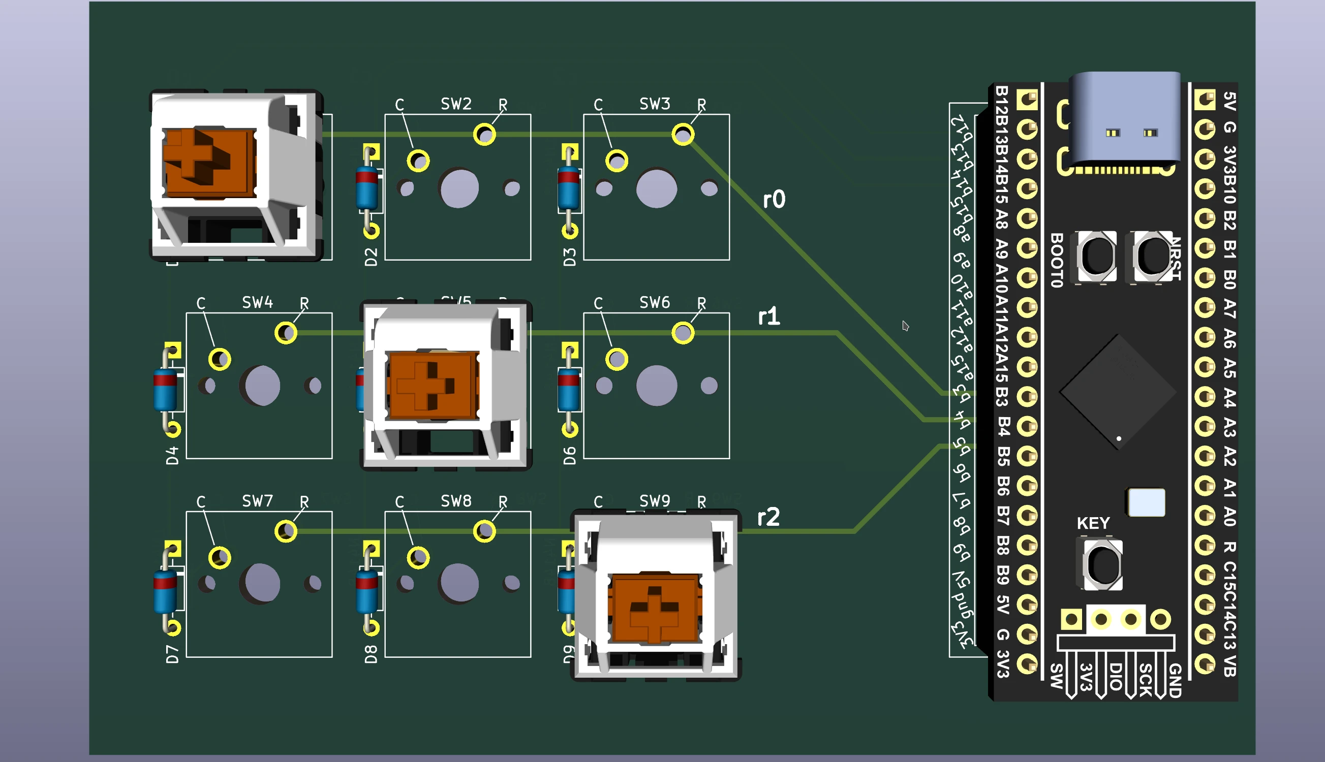
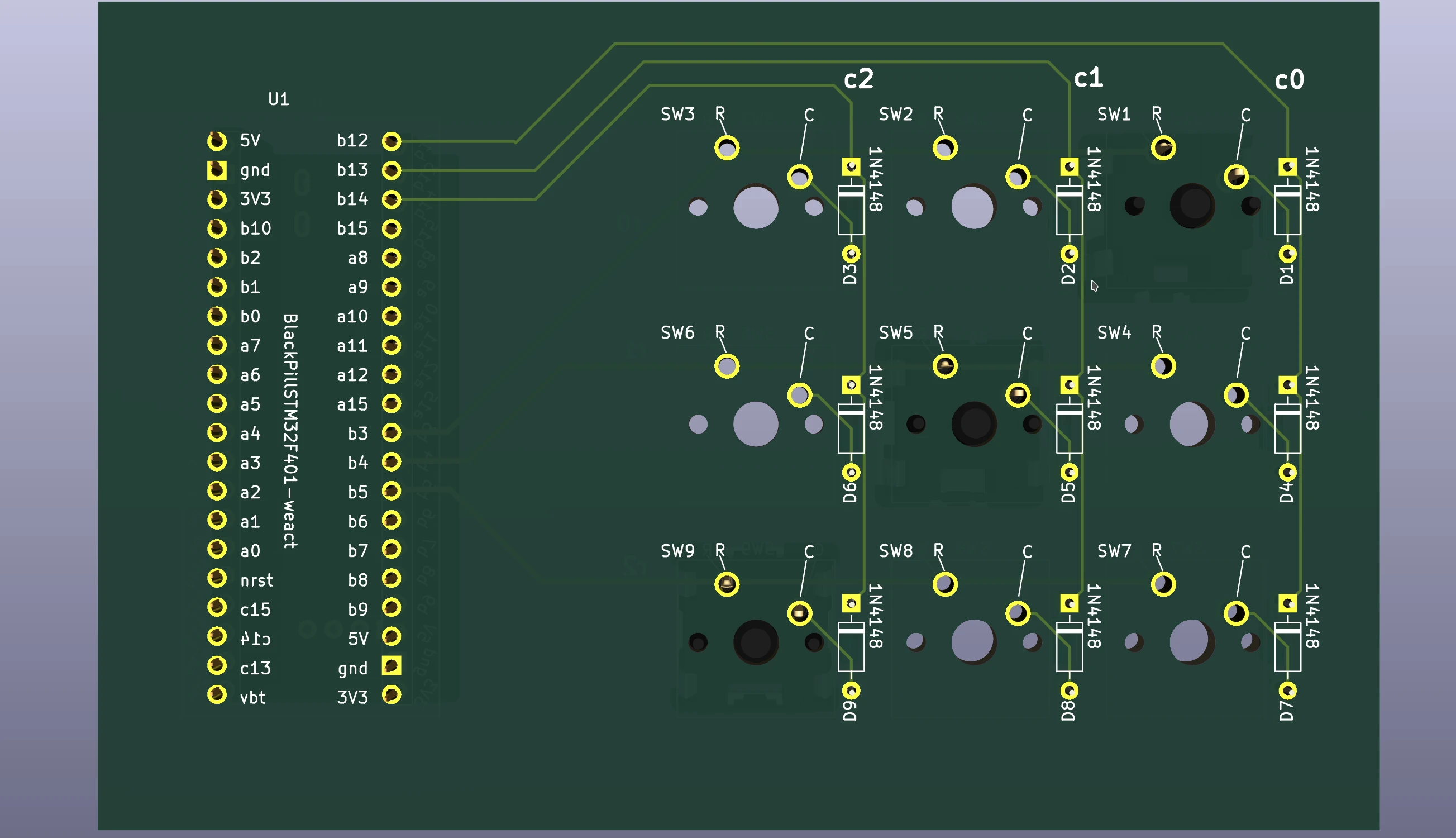
Side-by-Side PCB Comparison (COL2ROW vs. ROW2COL)
| View | COL2ROW (Column → Row) |
ROW2COL (Row → Column) |
|---|---|---|
| KiCad Routed Tracks | 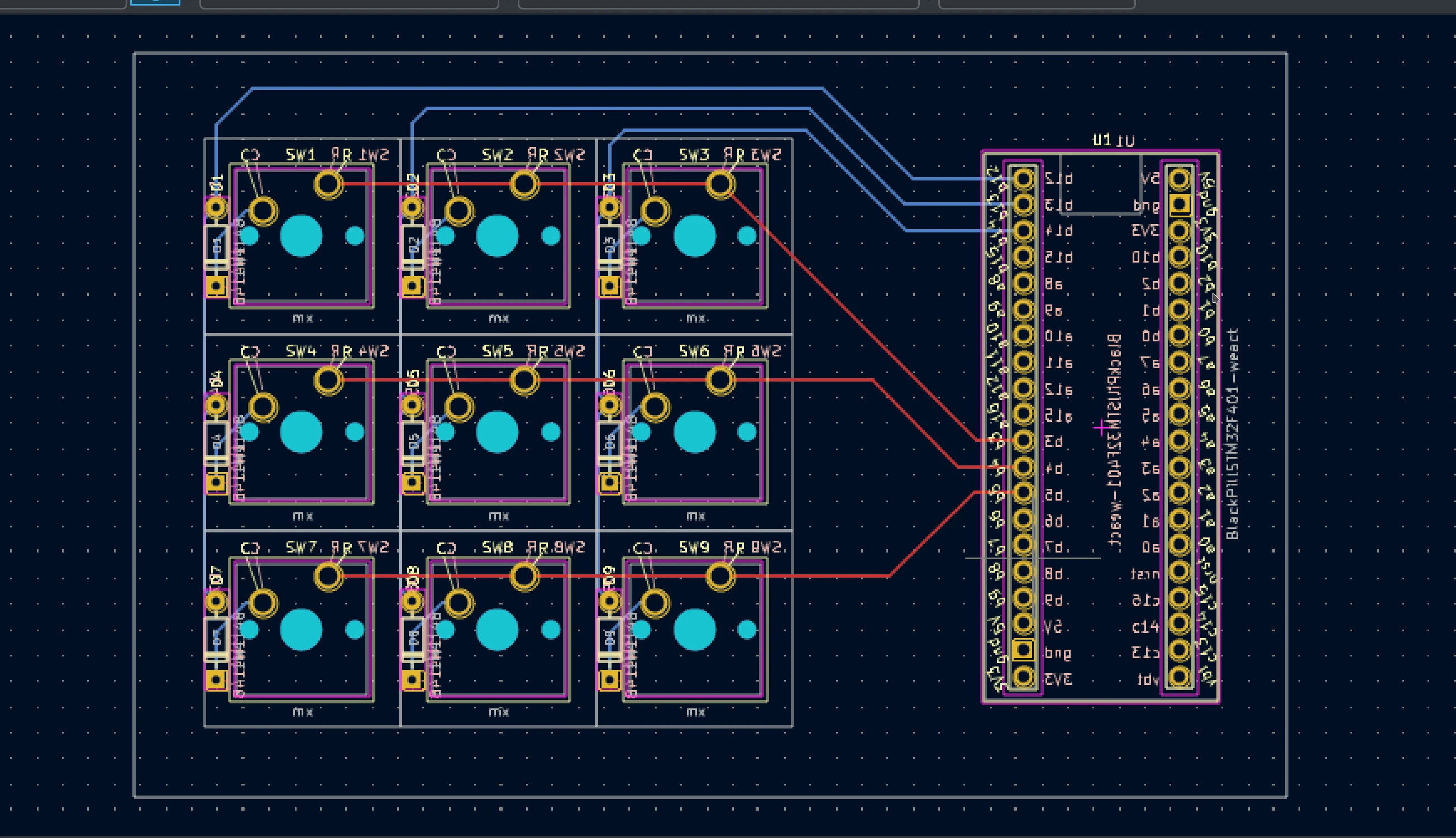 |
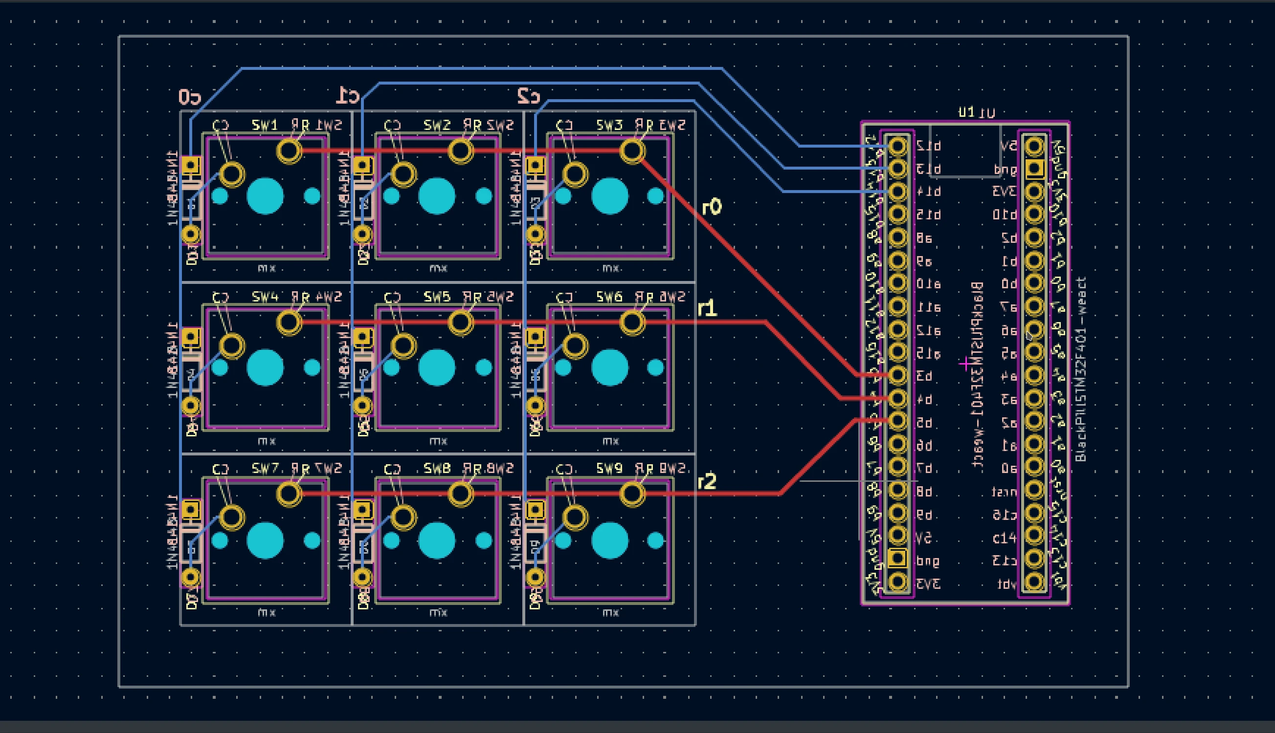 |
| 3D Render (Front) | 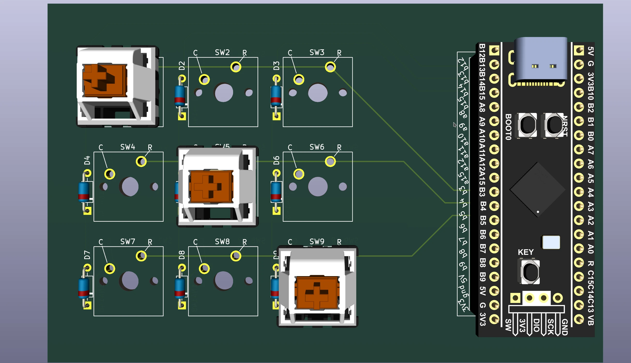 |
 |
| 3D Render (Bottom) | 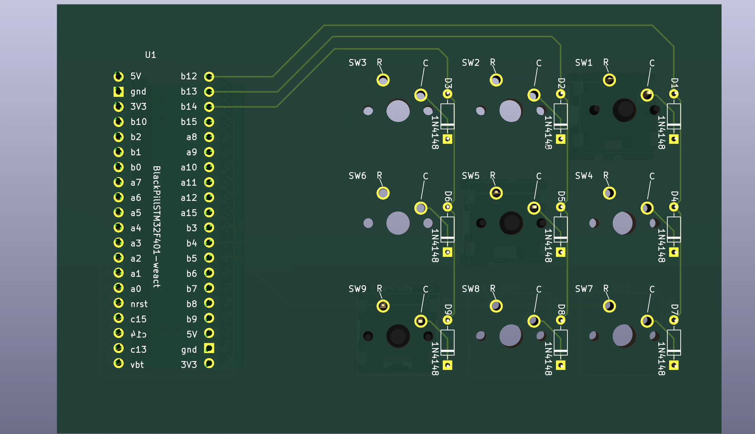 |
 |