m66 — 5×14 LEGO Ortholinear Keyboard
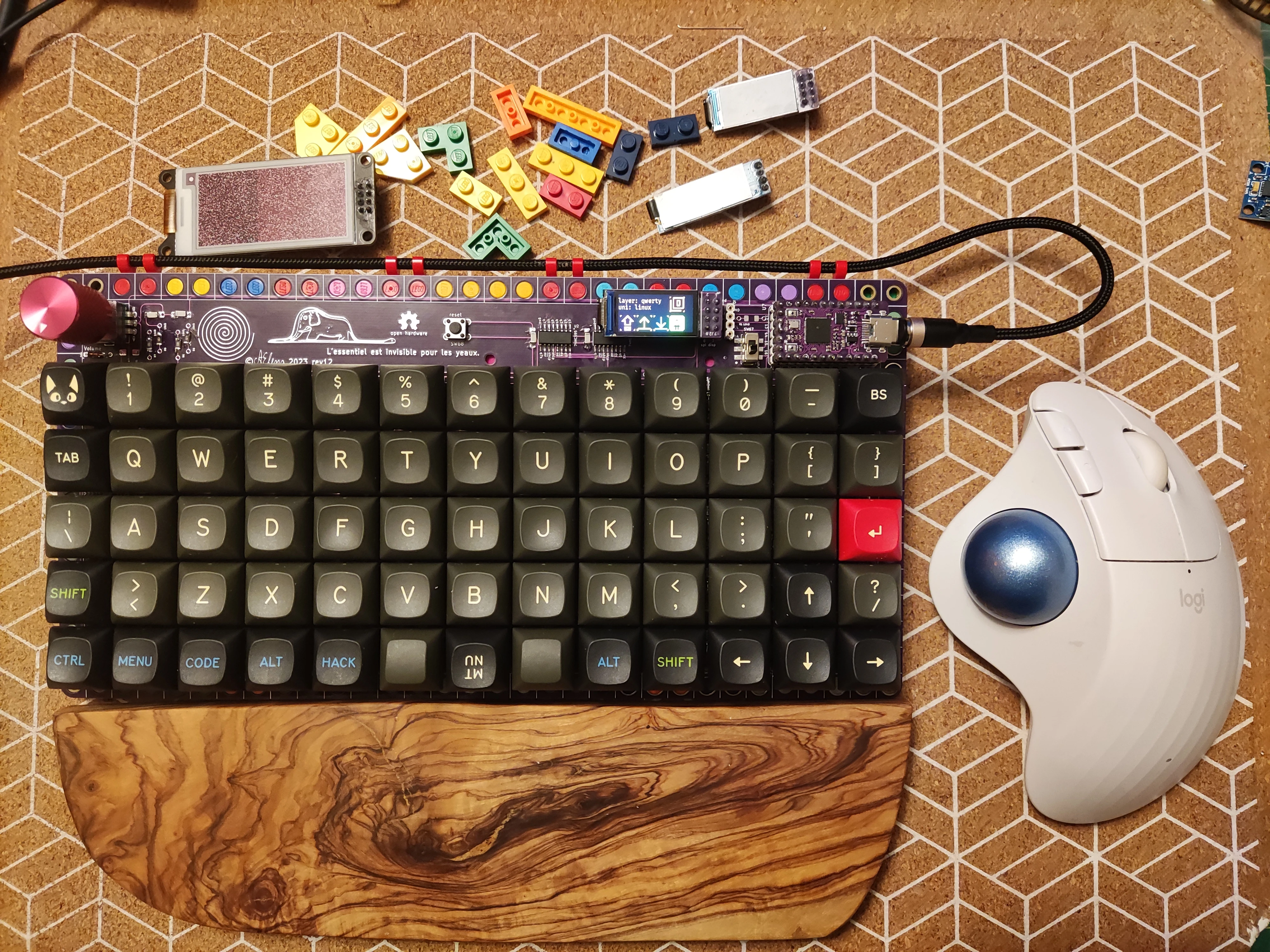
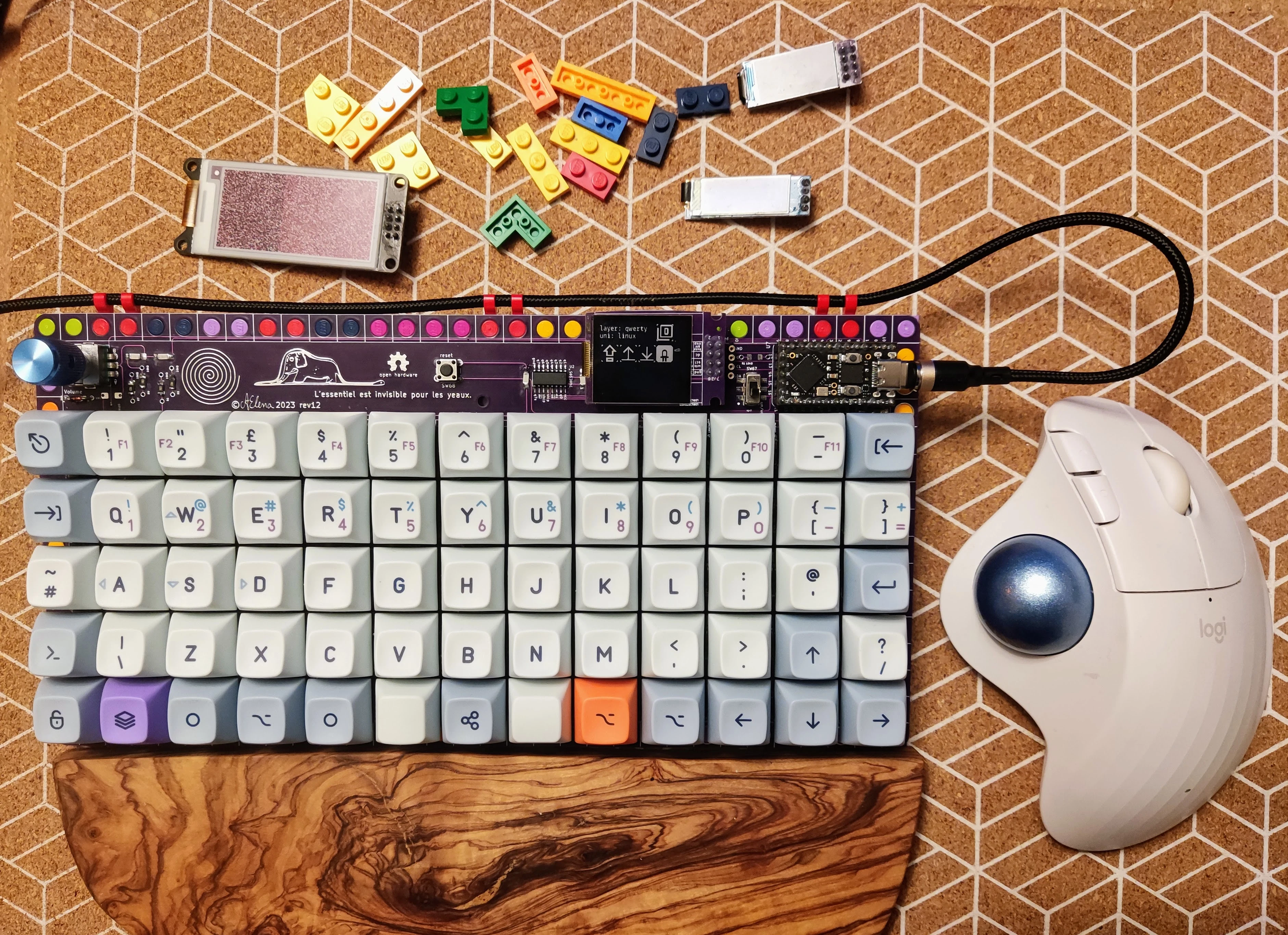
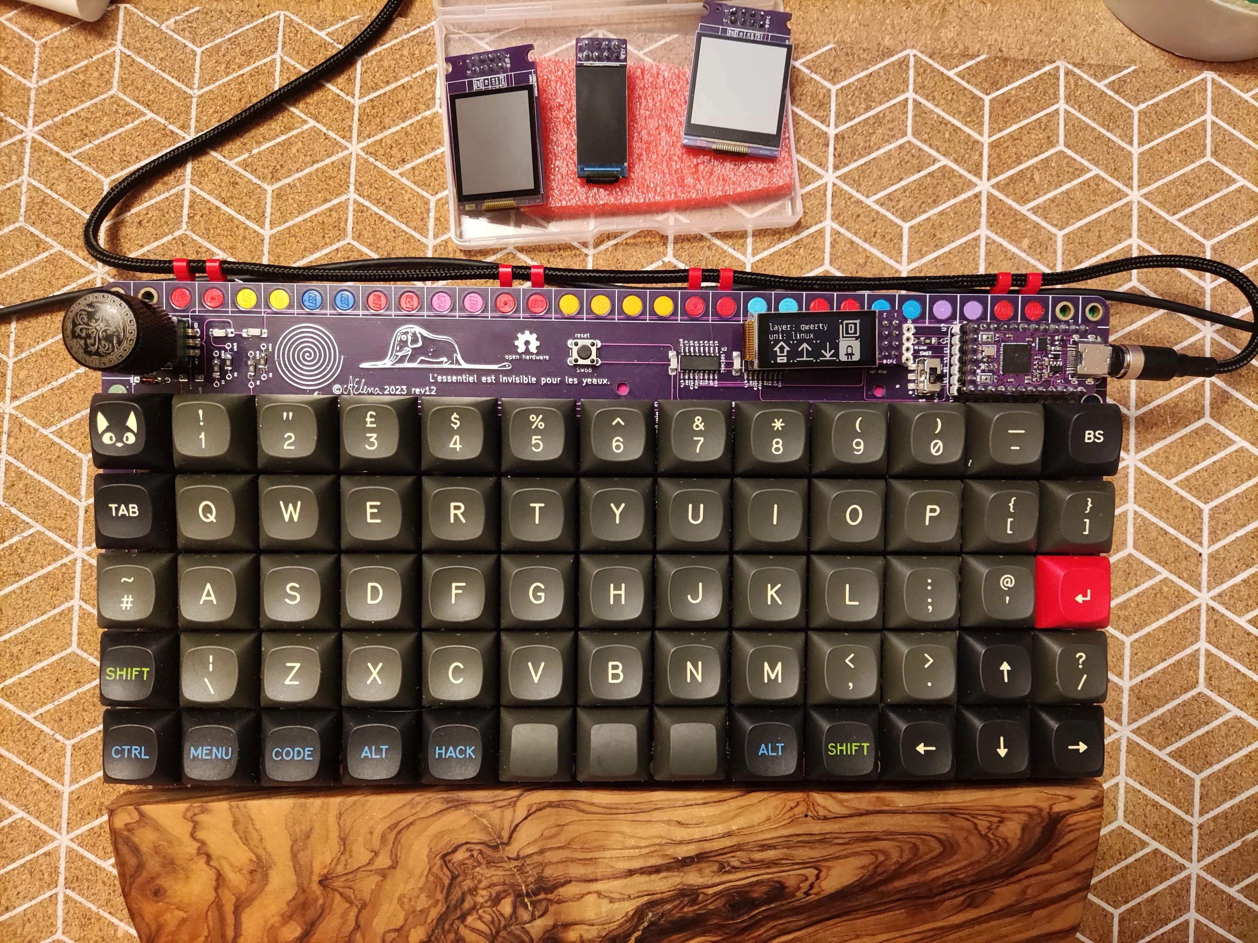
The m66 is a 5-row, 13-column ortholinear keyboard plus a dedicated clickable rotary encoder column (technically a 5×14 matrix), designed to accommodate all standard keycaps from an ISO layout.
The current iteration (Rev 4) uses an RP2040 Pro Micro–compatible footprint (tested with Splinky, Helios, and nice!nano BLE boards), chained per-key RGB LEDs and underglow backlight, a clickable rotary encoder, and multi-display support for I²C OLED, Sharp Memory display, WeAct SSD1680 e-ink, and ST7735 IPS LCD screens.
Status: Rev 4 Done and Tested
* [x] Gerbers designed
* [x] Firmware (QMK & ZMK)
* [ ] Breadboard tested
* [x] Gerbers printed
* [x] Board tested
Revision History
* **m66 Rev 4** *(formerly m65 Rev 12)*: RP2040 Pro Micro pinout with 2× `74HC595` shift registers, OLED / LCD (`ST7735` tested) / Sharp Memory / e-ink (`SSD1680` WeAct), clickable encoder, per-key RGB, and RGB backlight
* **m66 Rev 3** *(formerly m65 Rev 11)*: XIAO RP2040 with 3 shift registers (2× `74HC595` + 1× `74HC589`), OLED / e-ink (`SSD1680` WeAct), and push rotary encoder with QMK (ZMK support in progress for RP2040 and nRF52840)
* **m66 Rev 2** *(formerly m65 Rev 10)*: XIAO RP2040 with 3 shift registers (2× `74HC595` + 1× `74HC589`), OLED, and push rotary encoder with QMK
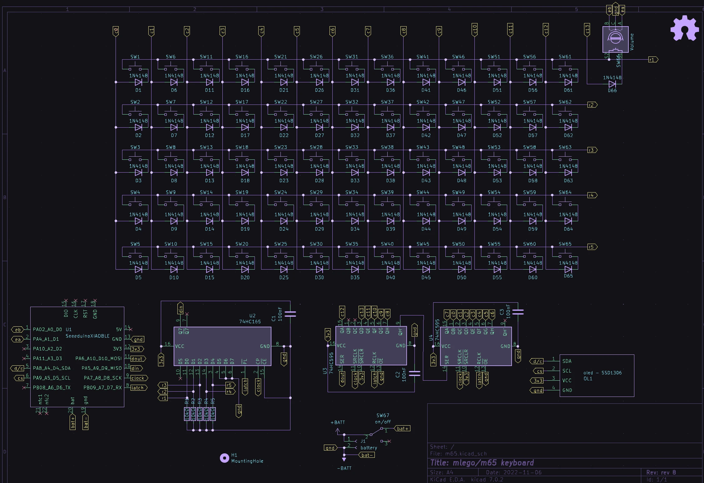
* **m66 Rev 1** *(formerly m65 Rev 9)*: XIAO RP2040 with 3 shift registers (2× `74HC595` + 1× `74HC165`), OLED, and push rotary encoder with QMK
* **m65 Rev 7/8**: XIAO RP2040 and nRF52840 with 2× `74HC595` shift registers, rotary encoder, no OLED (both QMK and ZMK firmware on RP2040)
* **m65 Rev 5/6**: RP2040 support (Raspberry Pi Pico, WeAct, and compatible clones), non-push encoder, OLED
* **m65 Rev 4**: `STM32F401`/`F411`, non-push encoder, OLED
* **m65 Rev 3**: `STM32F401`/`F411`, non-push encoder
* **m65 Rev 2**: `GD32F303` (BluePill Plus, USB-C F103 equivalent — <https://github.com/WeActStudio/BluePill-Plus>)
* **m65 Rev 1**: `STM32F103` / `APM32F103` or `STM32F303`
BOM
Microcontroller Notes (MCUs)
I have used several reference MCU boards over time. Reference boards simplify DIY keyboard design since all high-frequency crystal and power circuitry is already on the module. While I have done handwire projects with AVR (`ATmega32U4`), I strongly advise against using them for new builds.

* **m65 Rev 1**: `STM32F103` [BluePill](https://stm32-base.org/boards/STM32F103C8T6-Blue-Pill.html) or [RobotDyn `STM32F303CCT6` BlackPill](https://stm32-base.org/boards/STM32F303CCT6-RobotDyn-Black-Pill.html) *(do not confuse with the WeAct F401/F411 BlackPill)*. Micro-USB; requires flashing an `stm32duino` bootloader.
* **m65 Rev 2**: `GD32F303` [BluePill Plus](https://github.com/WeActStudio/BluePill-Plus) with USB Type-C.
* **m65 Rev 3/4**: WeAct [`STM32F401`/`F411` MiniF4x BlackPill](https://github.com/WeActStudio/WeActStudio.MiniSTM32F4x) with USB Type-C.
* **m65 Rev 5/6**: `RP2040` ([Raspberry Pi Pico](https://www.raspberrypi.com/documentation/microcontrollers/raspberry-pi-pico.html), [Waveshare RP2040-Plus](https://www.waveshare.com/wiki/RP2040-Plus), or USB-C compatible clones with matching pinouts).
* **m65 Rev 7 / m66 Rev 1–3**: [Seeed Studio XIAO RP2040](https://wiki.seeedstudio.com/XIAO-RP2040/) and [XIAO BLE nRF52840](https://wiki.seeedstudio.com/XIAO_BLE/). Compact 14-pin footprint paired with SPI shift registers.
* **m66 Rev 4**: `RP2040` in Pro Micro footprint (tested with **Splinky** and **Helios** pinouts) as well as **`nice!nano`** BLE controllers and clones.
* **More pins**: If you need more direct GPIO pins in a compact package, check the [WeAct `STM32G431` CoreBoard](https://github.com/WeActStudio/WeActStudio.STM32G431CoreBoard) (supported in QMK).
Rev 4
Revision 4 BOM
* **MCU**: `RP2040` Pro Micro–compatible pinout (tested with Splinky and Helios-like MCUs) or `nice!nano` BLE MCUs
* **Shift Registers**: 2× `74HC595` (SOIC-16 surface mount)
* **Diodes**: 66× `1N4148` signal diodes (DO-35 through-hole or SOD-123 SMD)
* **Display (optional)**: I²C OLED (128×32), Sharp Memory Display, ST7735 IPS LCD, or WeAct SSD1680 e-ink module
* **Encoder**: Clickable EC11 rotary encoder (e.g., Bourns 24-pulse incremental mechanical encoder with 6 mm flat shaft)
* **RGB (optional)**: Per-key SK6812 MINI-E LEDs and/or underglow RGB chain
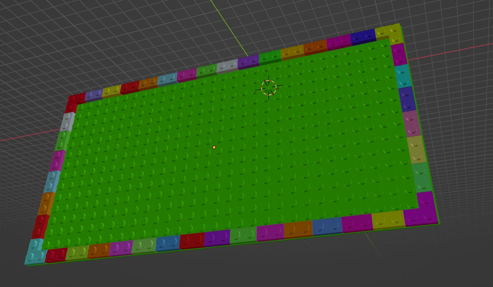
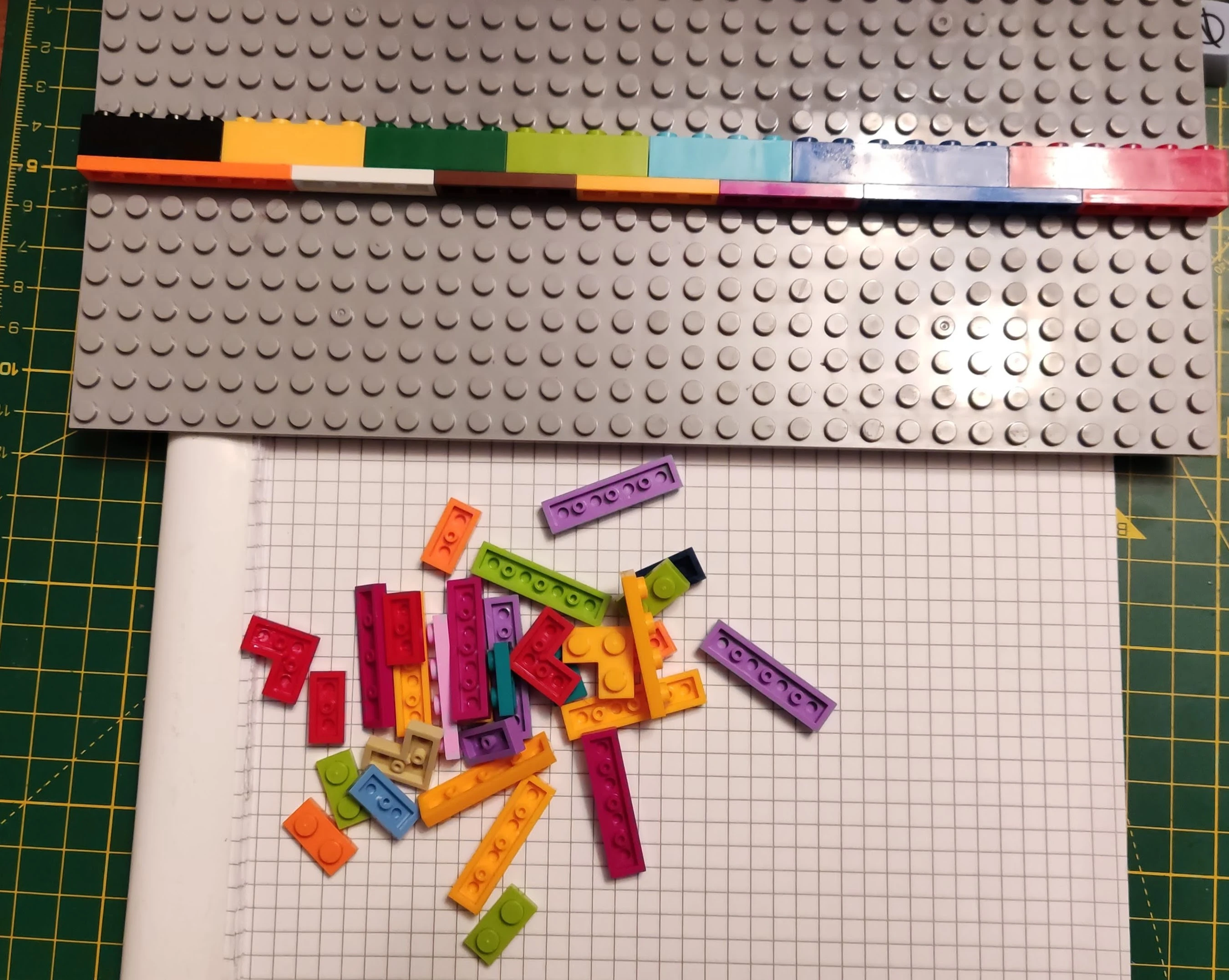
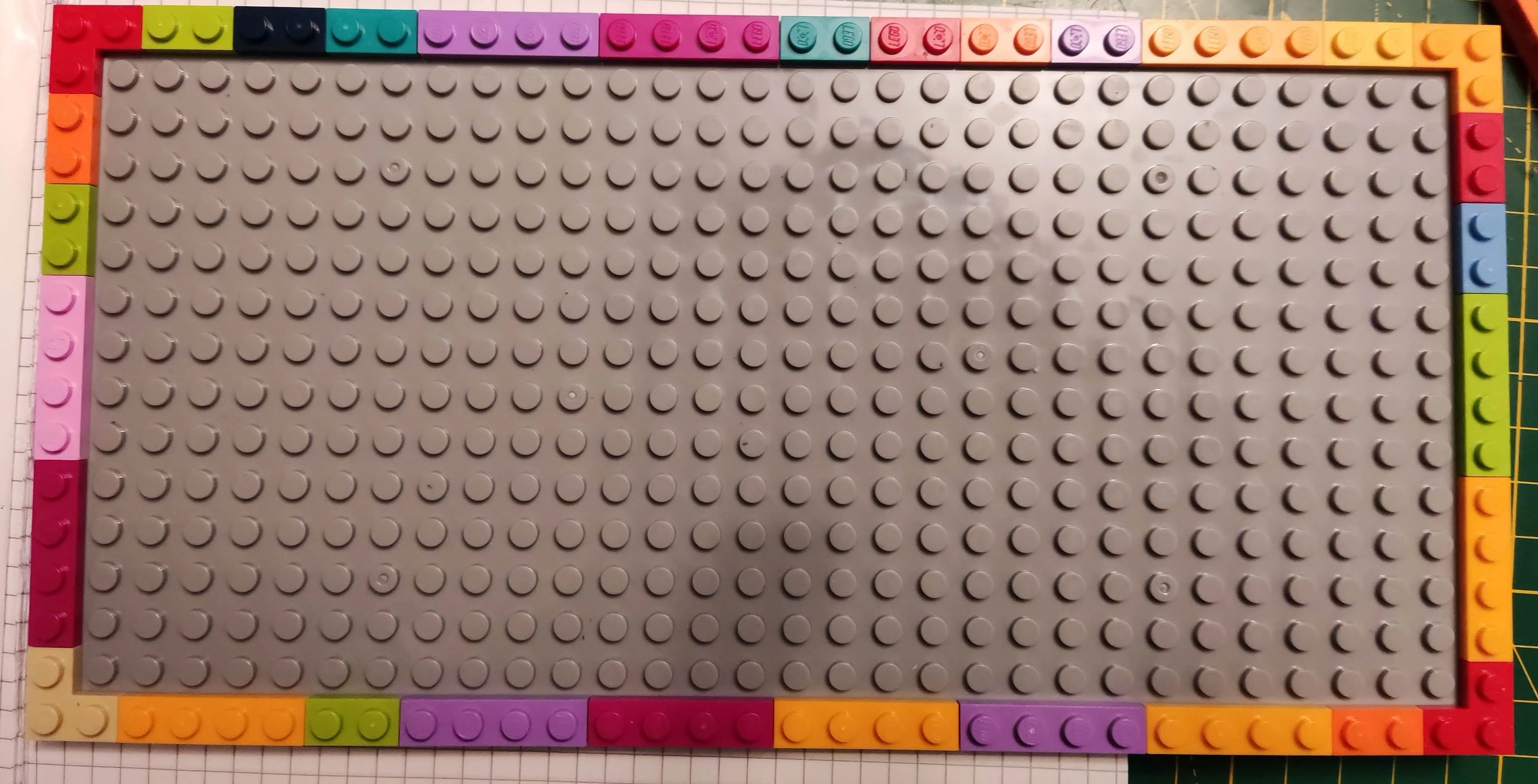
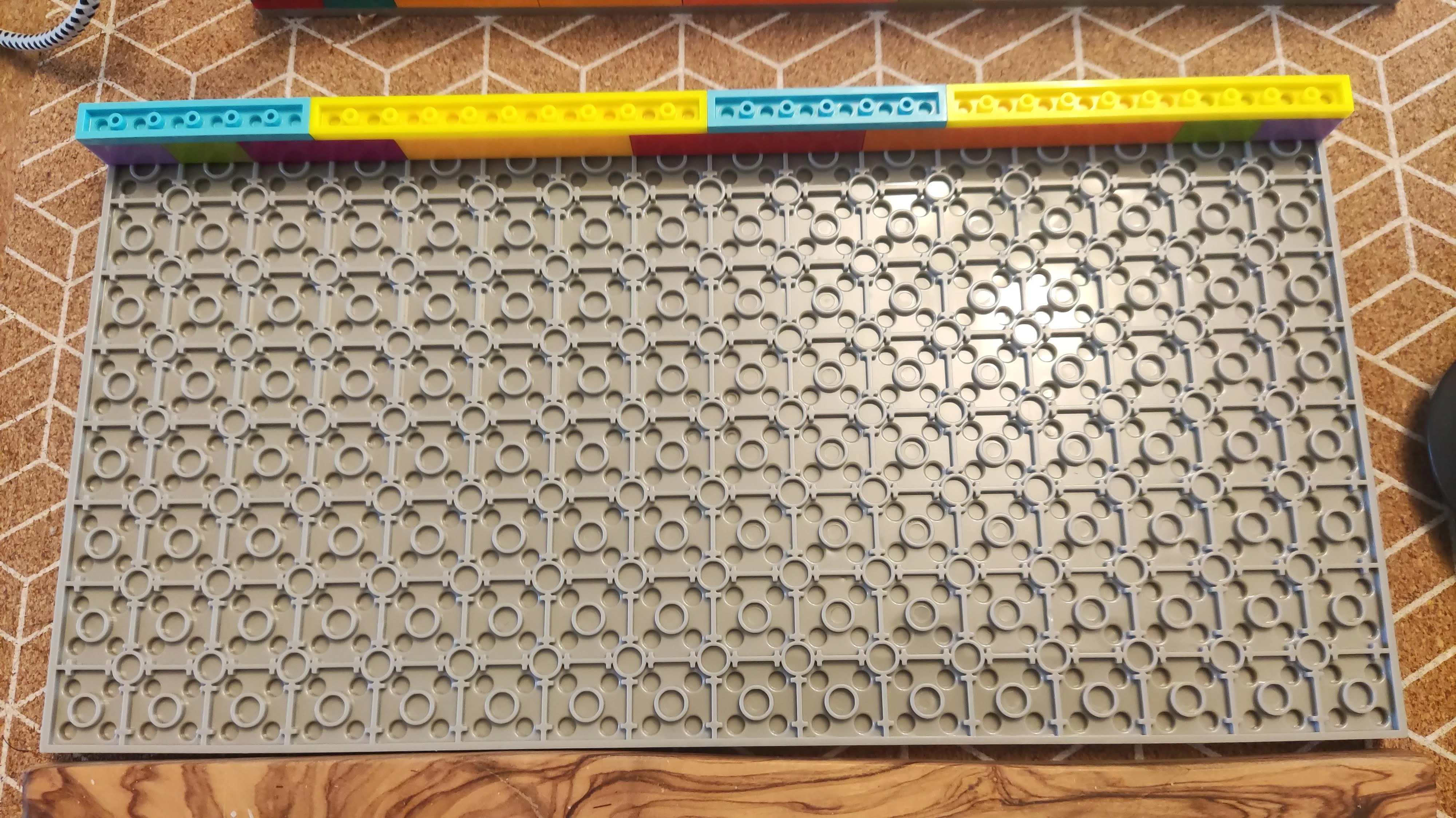
* **LEGO Enclosure**: 16×32 double-sided baseplate (or 2× 16×16 plates) + ~46× 1×2 or 1×4 LEGO plates/bricks
Rev 3
Revision 3 BOM (formerly m65 Rev 11)
* **LEGO**: ~46× 1×2 or 1×4 plates (or bricks if housing a LiPo battery), 1× 16×32 double-sided baseplate (or 2× 16×16 plates; gray plates minimize PCB bow), optional 4× 1×1 tiles/eyes and 4× 2×2 corner plates
* **Diodes**: 66× `1N4148` signal diodes (DO-35 or SOD-123)
* **Resistors**: 5× 10 kΩ (THT or SMD 1206) and 1× 5.1 kΩ (THT or SMD 1206)
* **MCU**: Seeed Studio XIAO RP2040 (or XIAO nRF52840) with recommended female header sockets
* **Shift Registers**: 2× `74HC595` (SOIC-16 SMD) and 1× `74HC589` (SOIC-16 SMD)
* **Transistor**: 1× `2N7002` N-channel MOSFET (SOT-23 SMD)
* **Capacitors (optional)**: 3× 100 nF decoupling capacitors
* **Power / Battery (optional)**: Pogo pins, LiPo battery, 2-pin PH 2.0 battery connector, and 1P2T 4 mm micro slide switch
* **Encoder**: Clickable EC11 rotary encoder (Bourns 24-pulse, 6 mm flat shaft)
* **Display (optional)**: 128×32 I²C OLED (1×4 socket) or WeAct SSD1680 e-ink display (2×4 header/socket)
Rev 2
Revision 2 BOM — Superseded by Rev 3 (formerly m65 Rev 10)
* Same component list as **Rev 3**, supporting I²C OLED (128×32) with 1×4 DIL socket (prior to the dedicated e-ink header addition in Rev 3).
Rev 1
Revision 1 BOM (formerly m65 Rev 9)
* **LEGO**: 16×32 double-sided plate (or 2× 16×16) + ~46× 1×2 or 1×4 plates
* **Diodes**: 66× `1N4148` signal diodes (DO-35 or SOD-123)
* **Resistors**: 5× 10 kΩ THT resistors
* **MCU**: Seeed Studio XIAO RP2040 (or XIAO nRF52840)
* **Shift Registers**: 2× `74HC595` (DIP-16 THT + sockets) and 1× `74HC165` (DIP-16 THT + socket)
* **Capacitors (optional)**: 3× 100 nF decoupling capacitors (or integrated capacitor DIP sockets)
* **Encoder & Battery**: EC11 clickable rotary encoder, optional LiPo battery + PH 2.0 socket + 1P2T switch
Case & Enclosure
Assembly
See the step-by-step Assembly Guide for soldering diodes, socketing the MCU and display, and mounting the PCB onto the LEGO baseplate.
Thickness Profiles
Depending on your LEGO plate stack, the enclosure can be built ultra-low-profile or tall enough to house underglow strips and batteries:
-
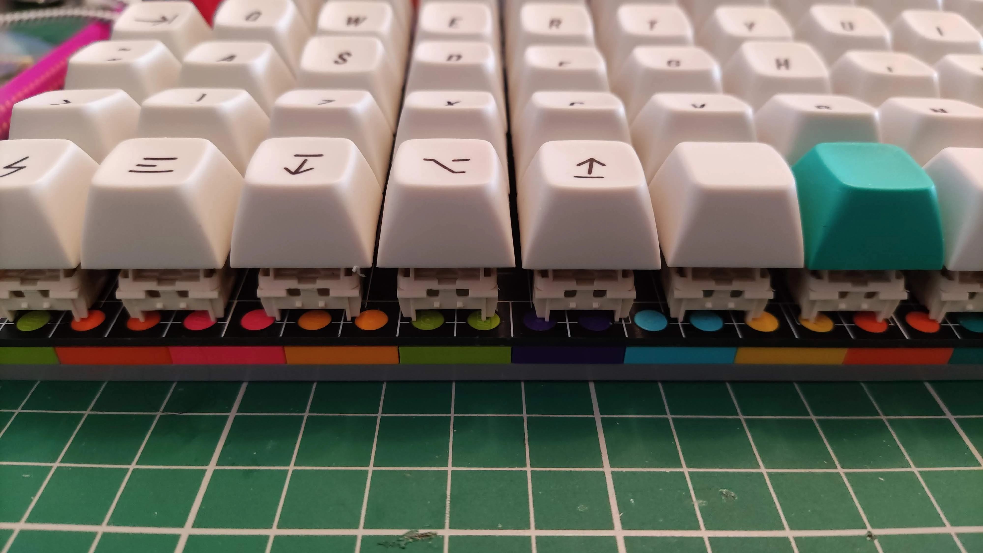
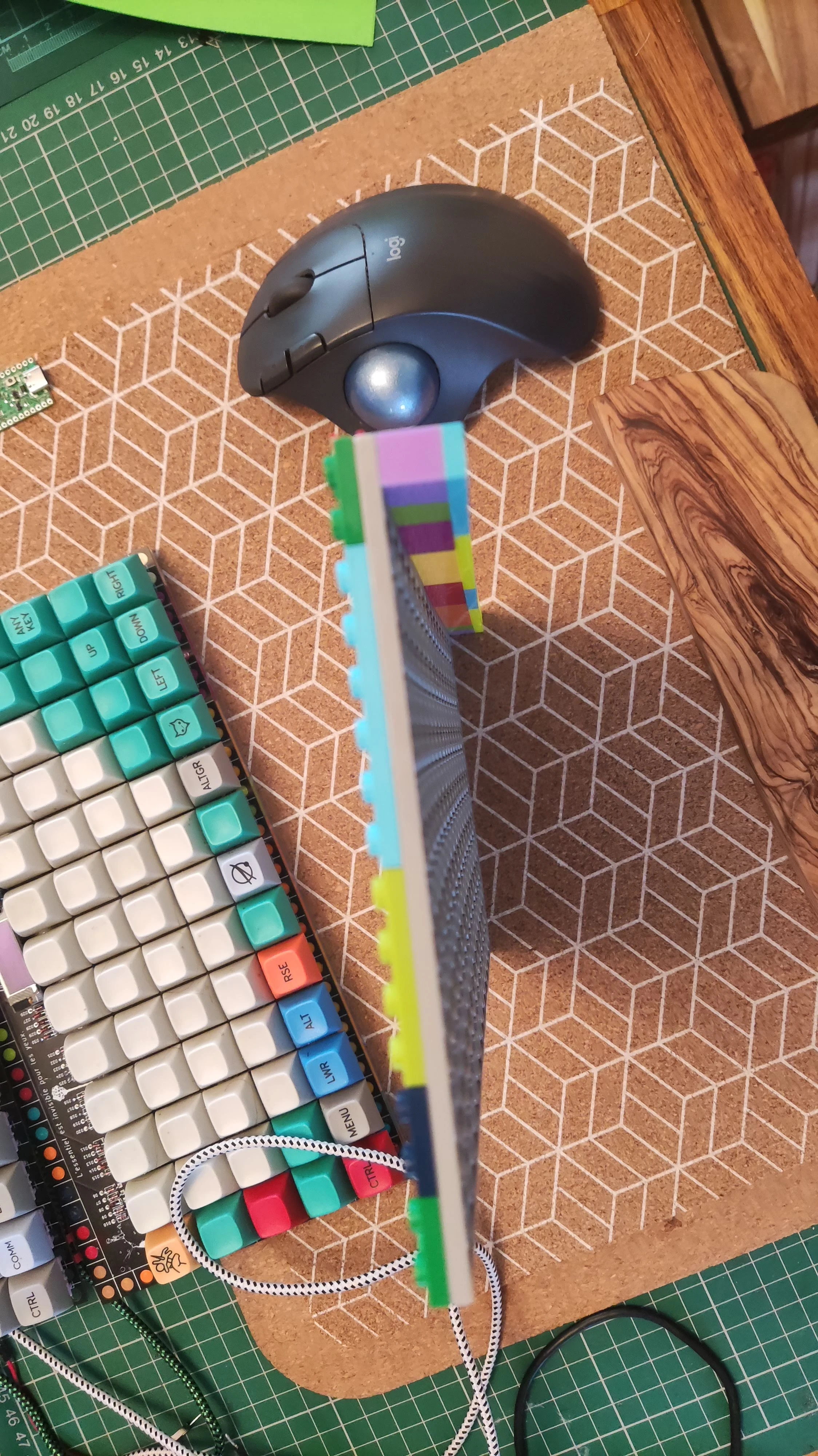
8.0 mm — Ultra-Thin Profile
1× double-sided baseplate + 1× intermediate plate (3.2 mm) + PCB (1.6 mm). Leaves room for a thin sheet of acoustic dampening foam.
-
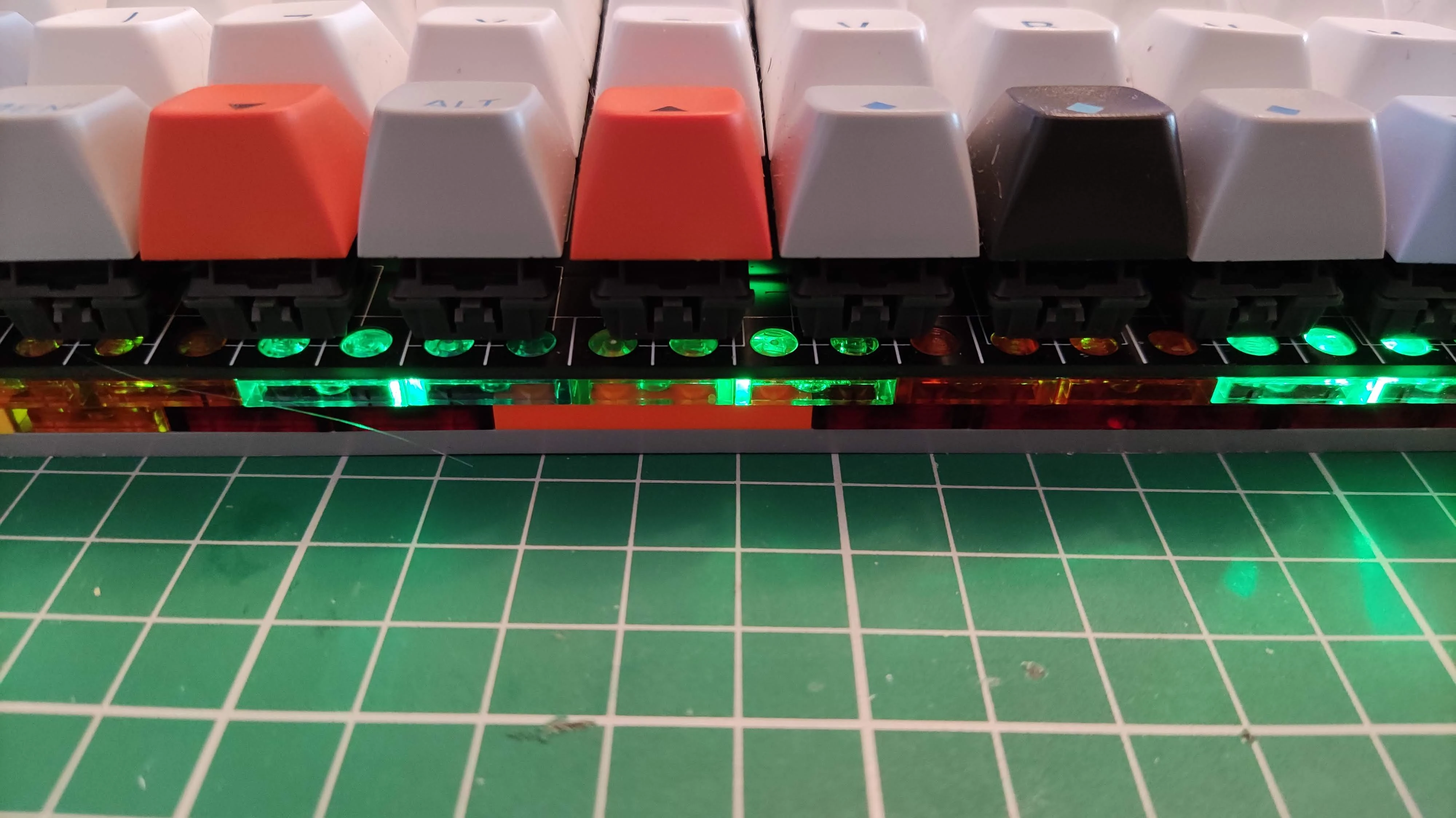
11.2 mm — Mid Profile
1× double-sided baseplate + 2× intermediate plates + PCB. Fits thicker foam or a direct-wired LED strip without a JST connector.
-
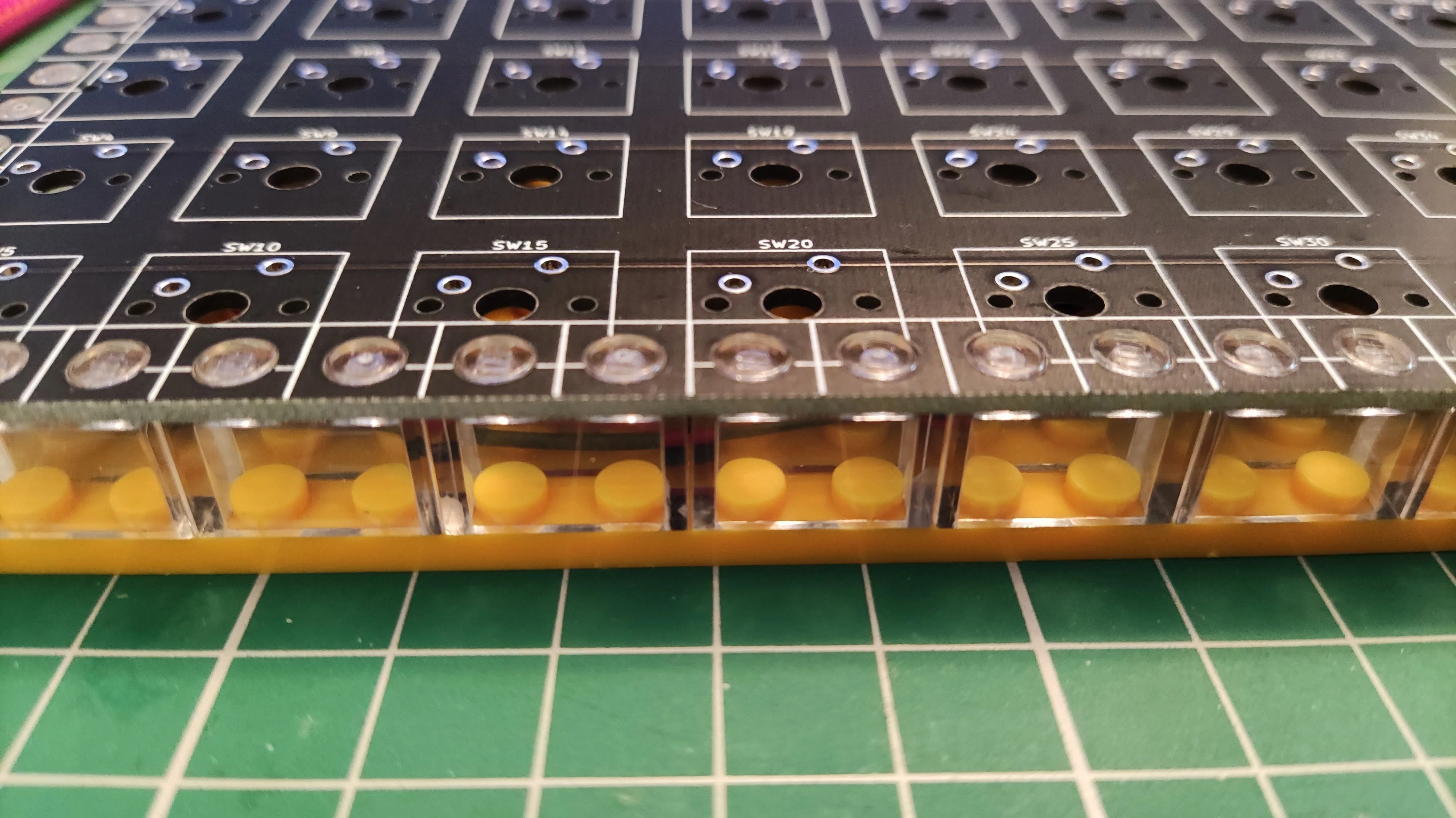
14.4 mm — Full Brick Profile
1× double-sided baseplate + 1× full LEGO brick + PCB. Accommodates a 3-pin JST header or LiPo battery.
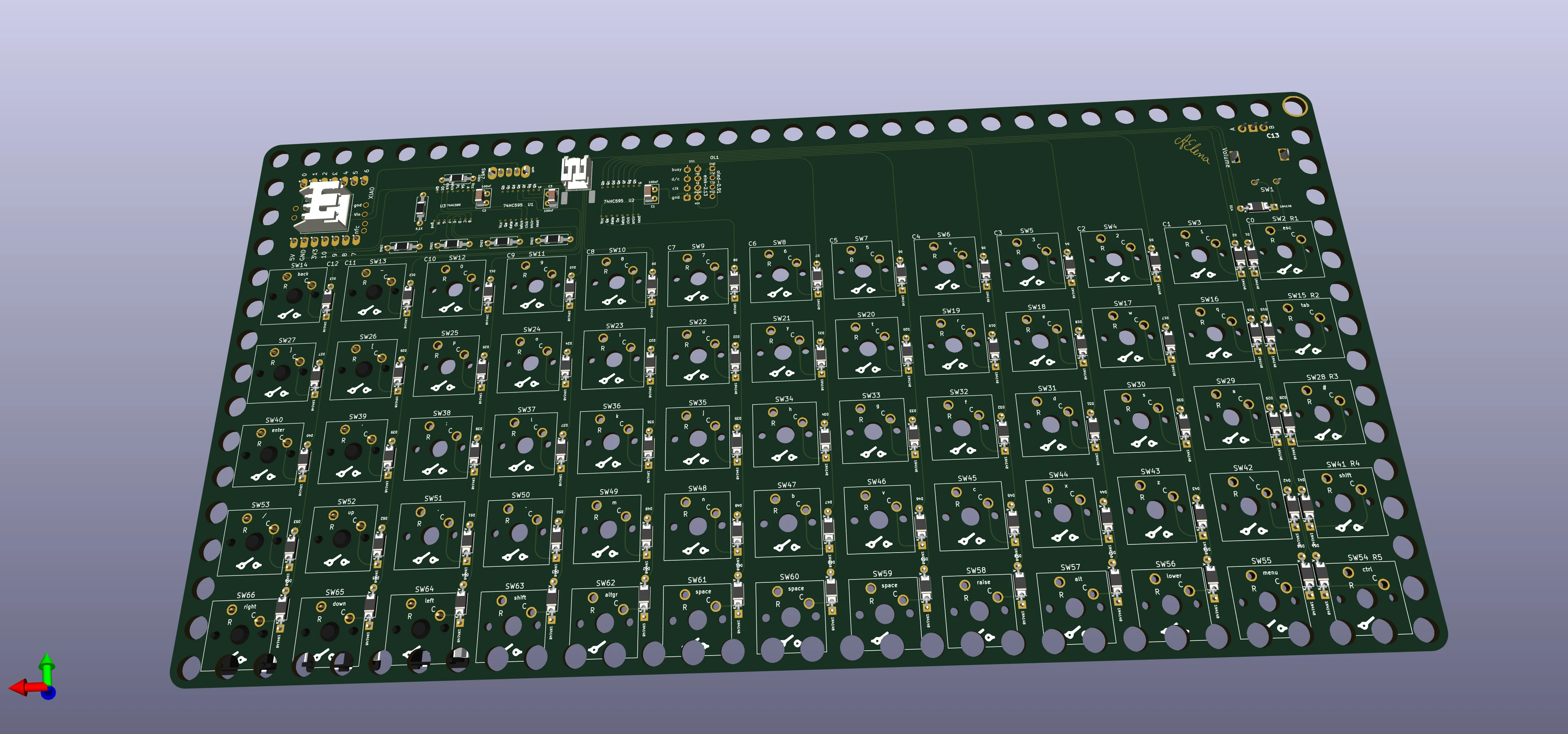
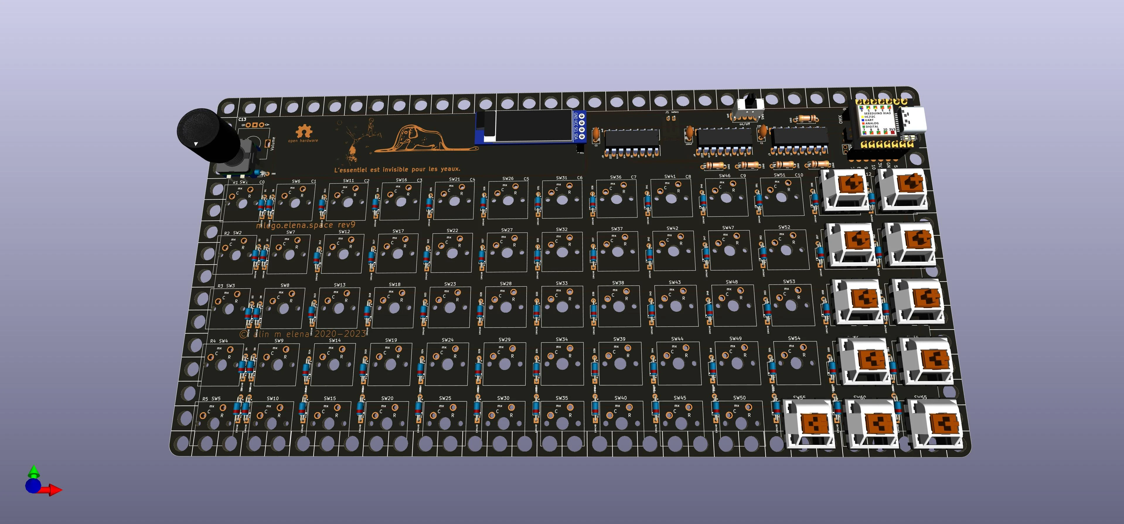
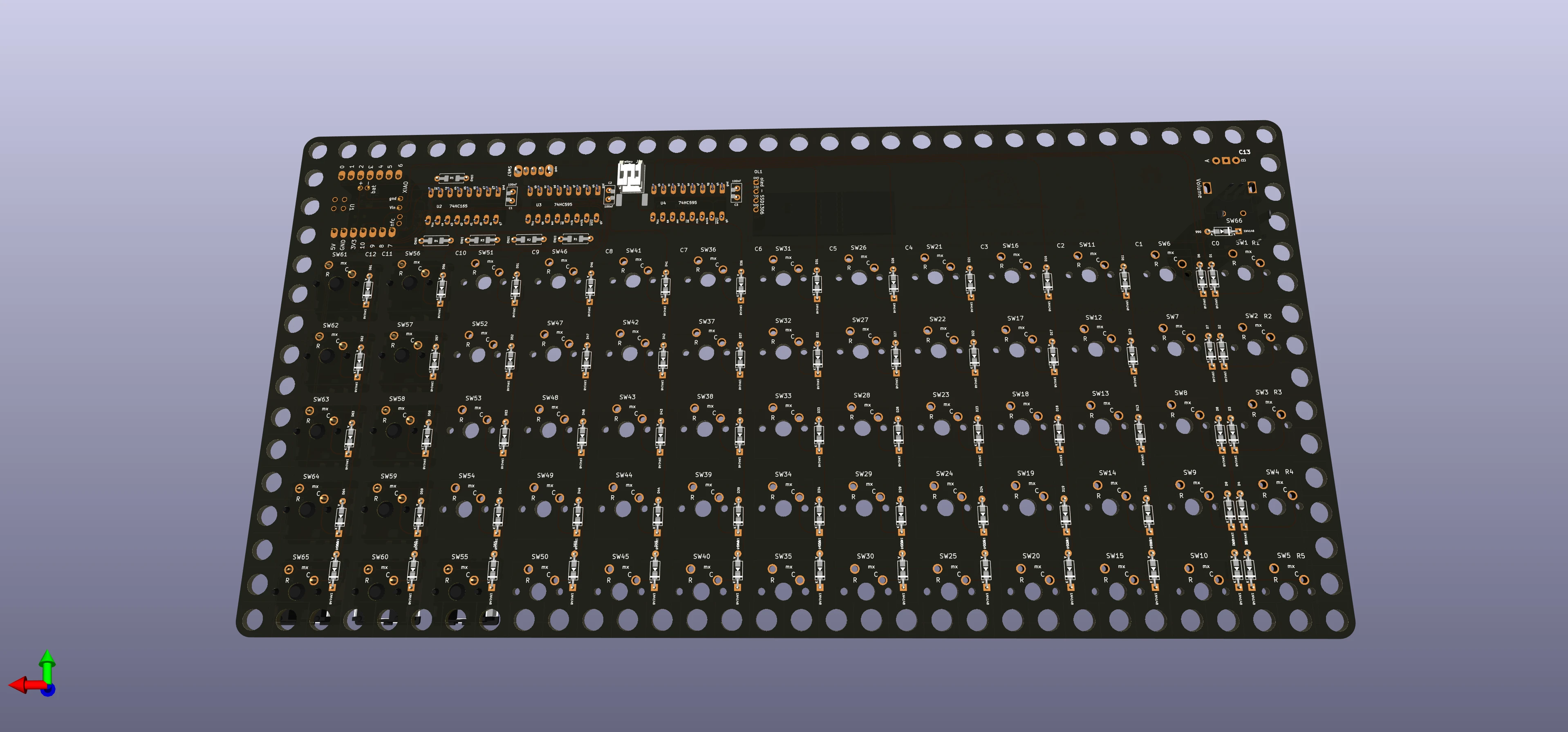
3D Renders
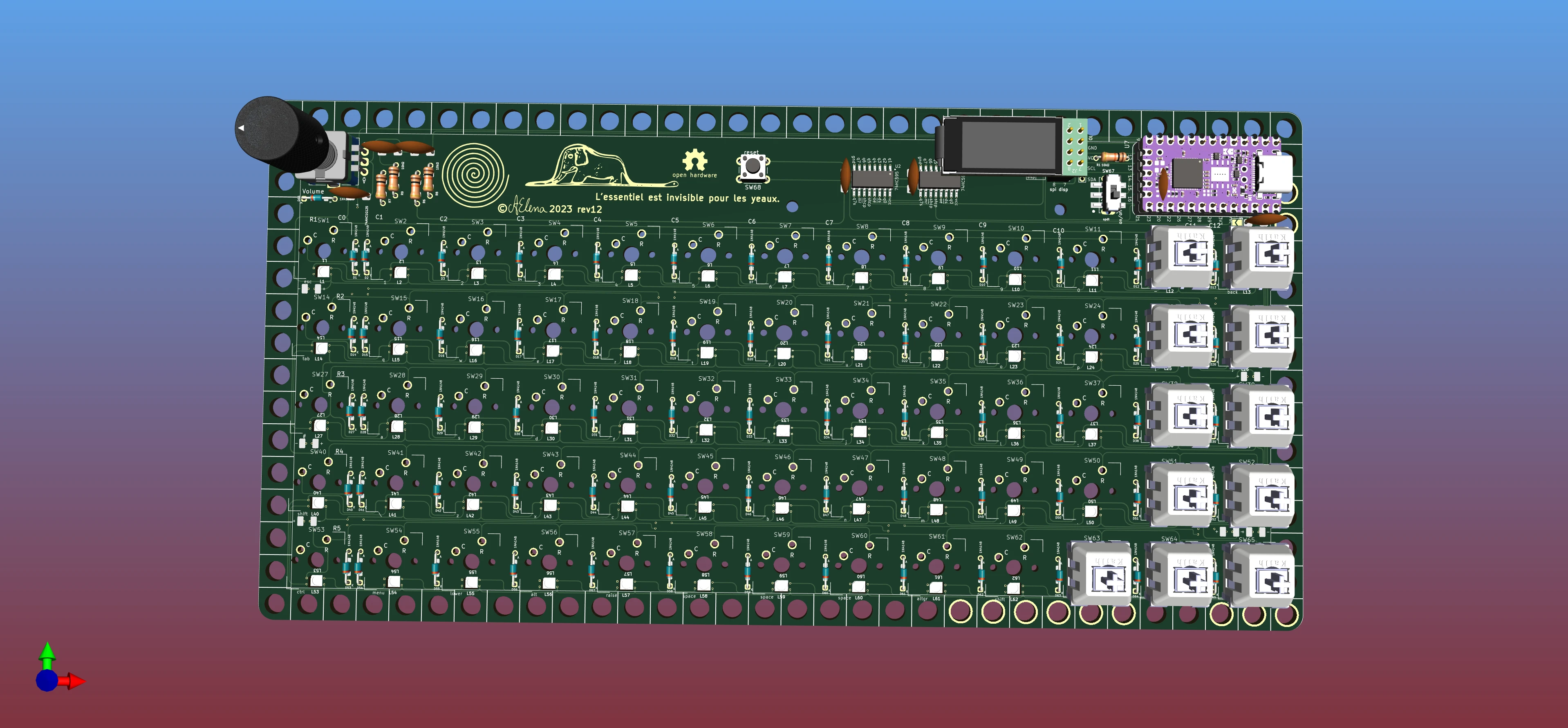
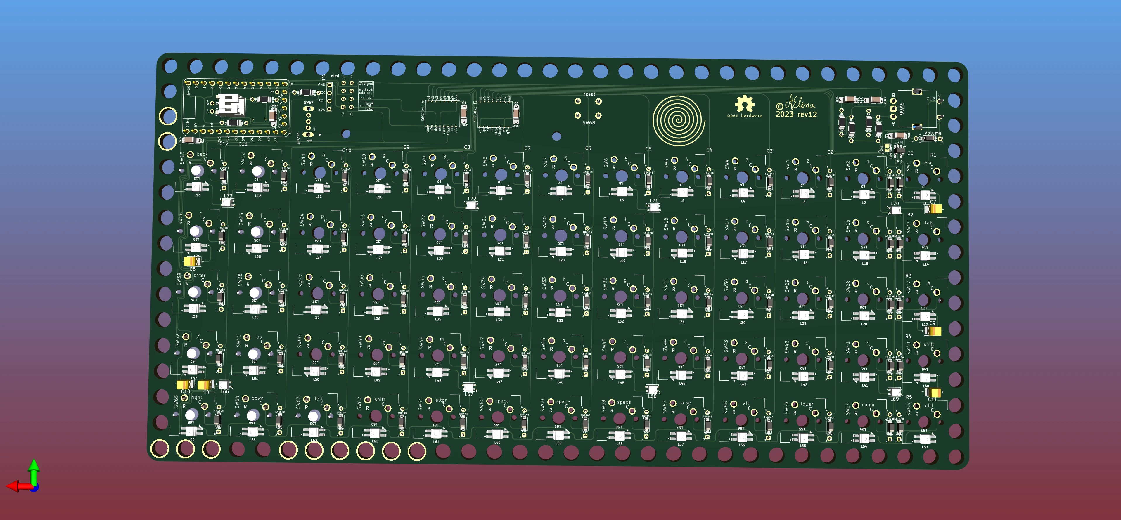
Rev 4
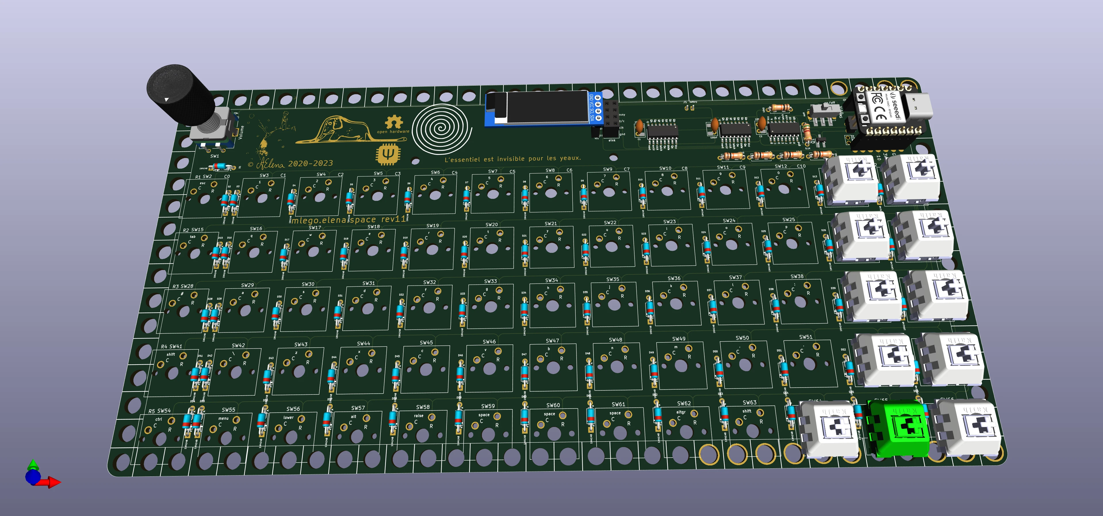
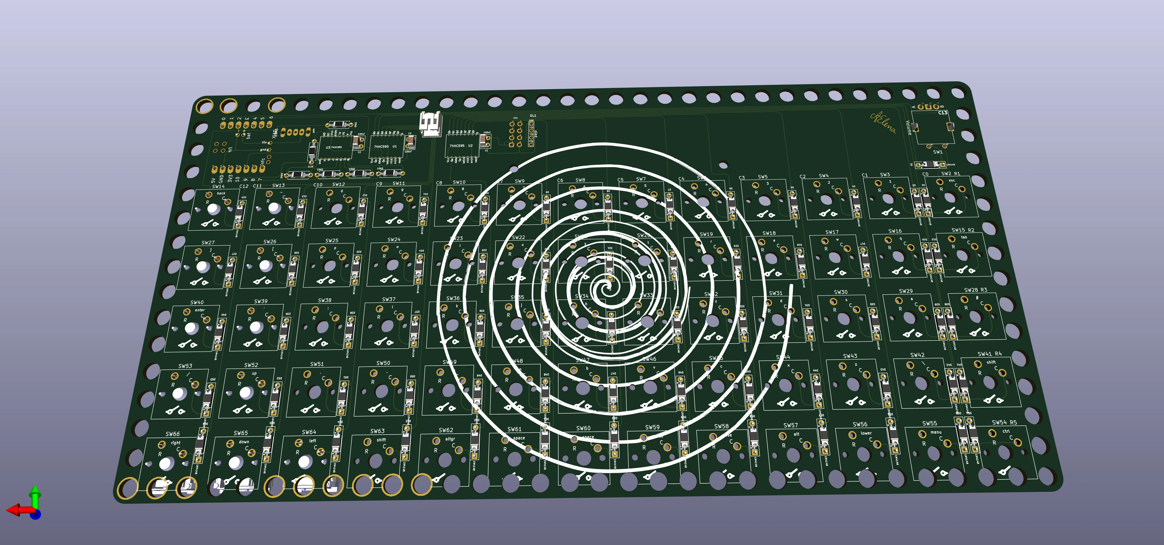
Rev 3
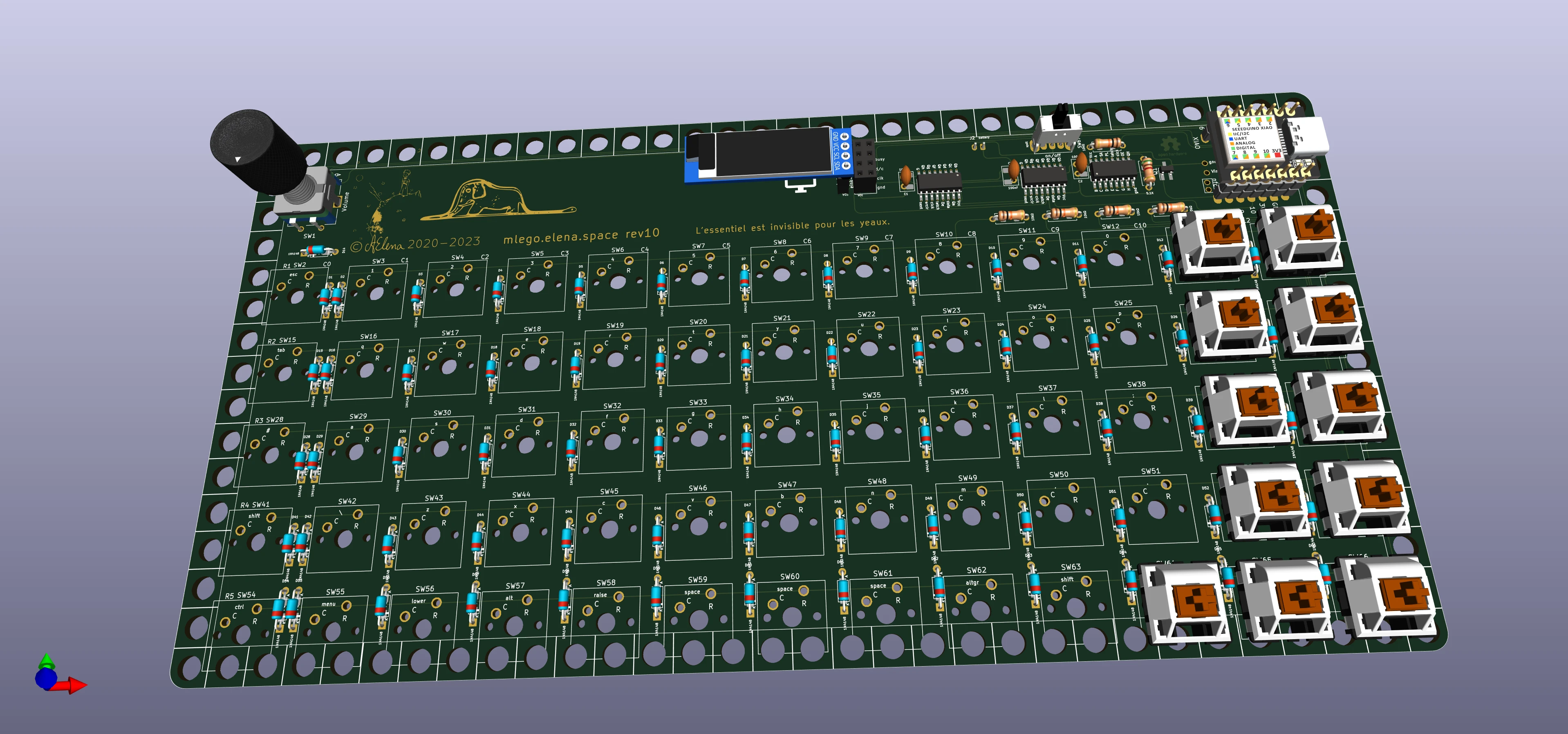
Rev 2
Rev 1
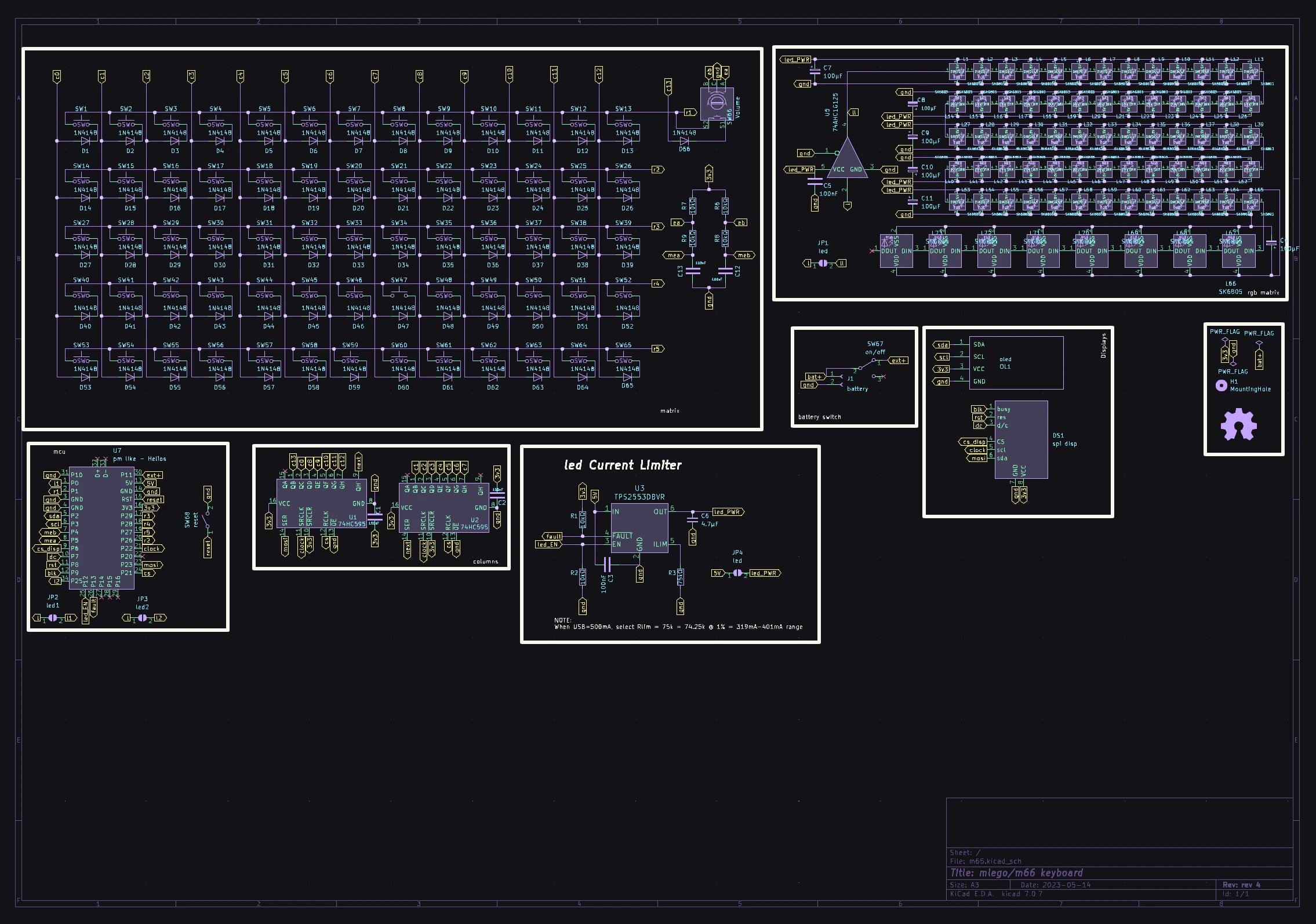
Schematics
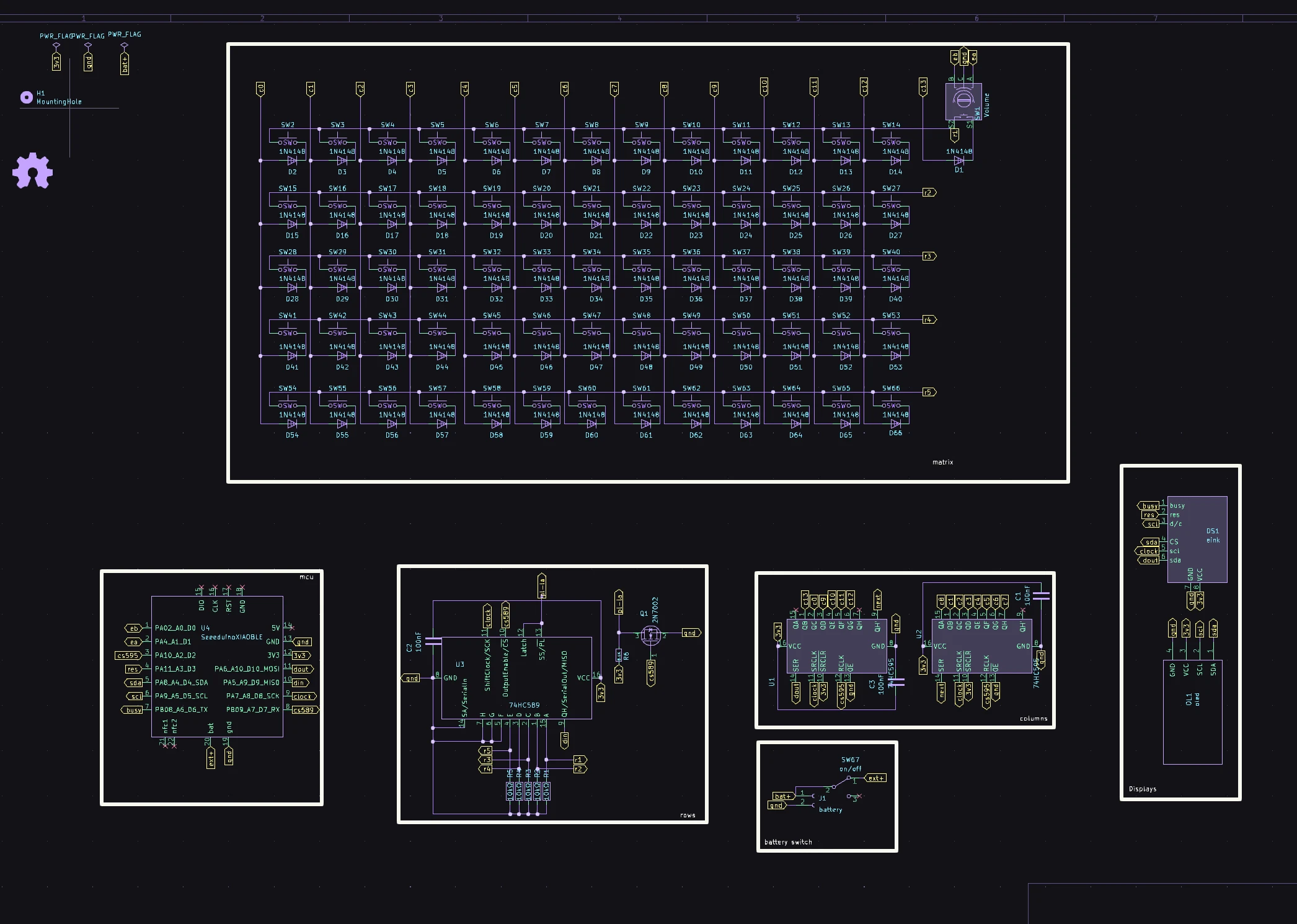
Rev 4
Rev 3
Rev 2

Rev 1
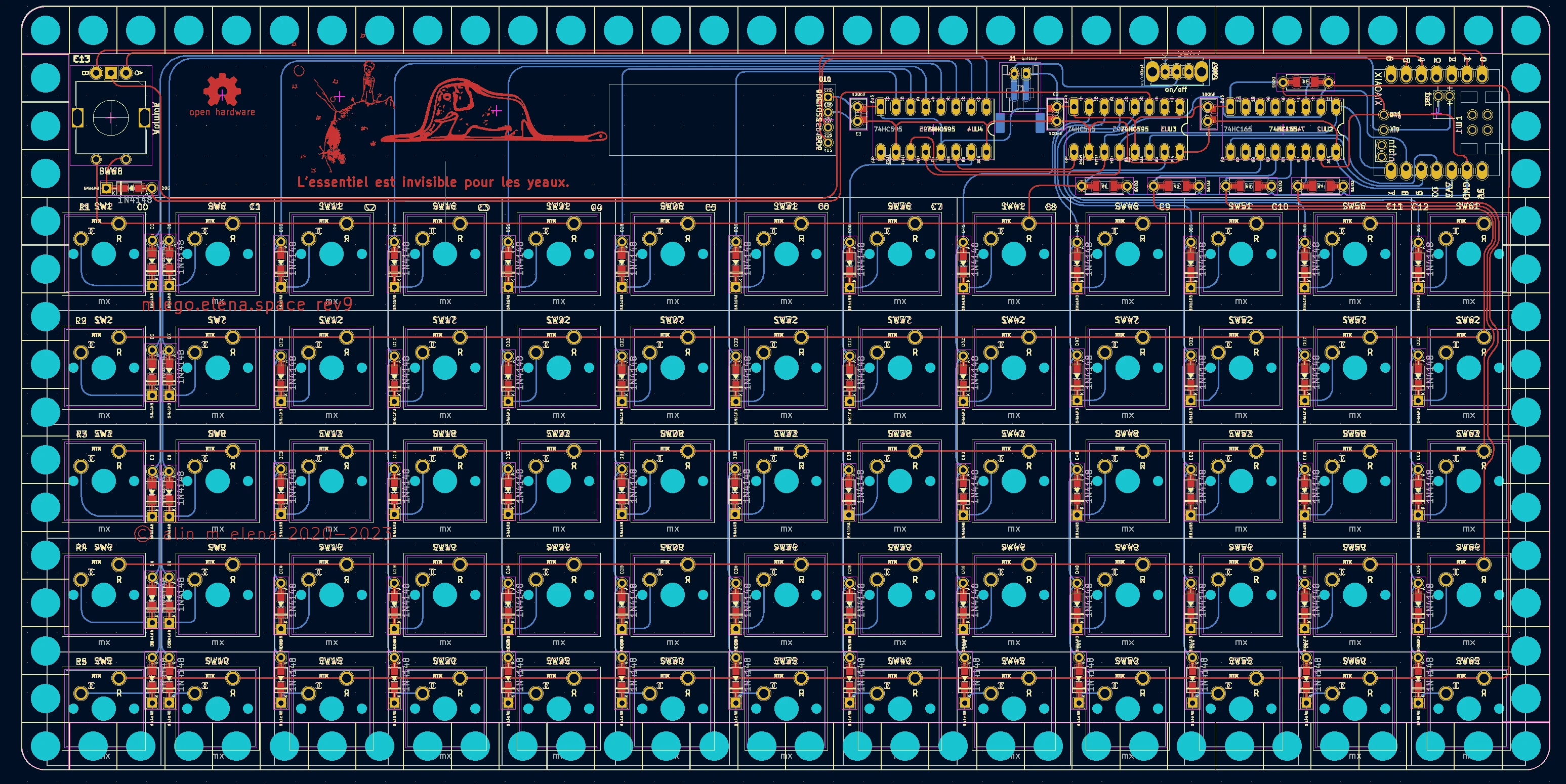
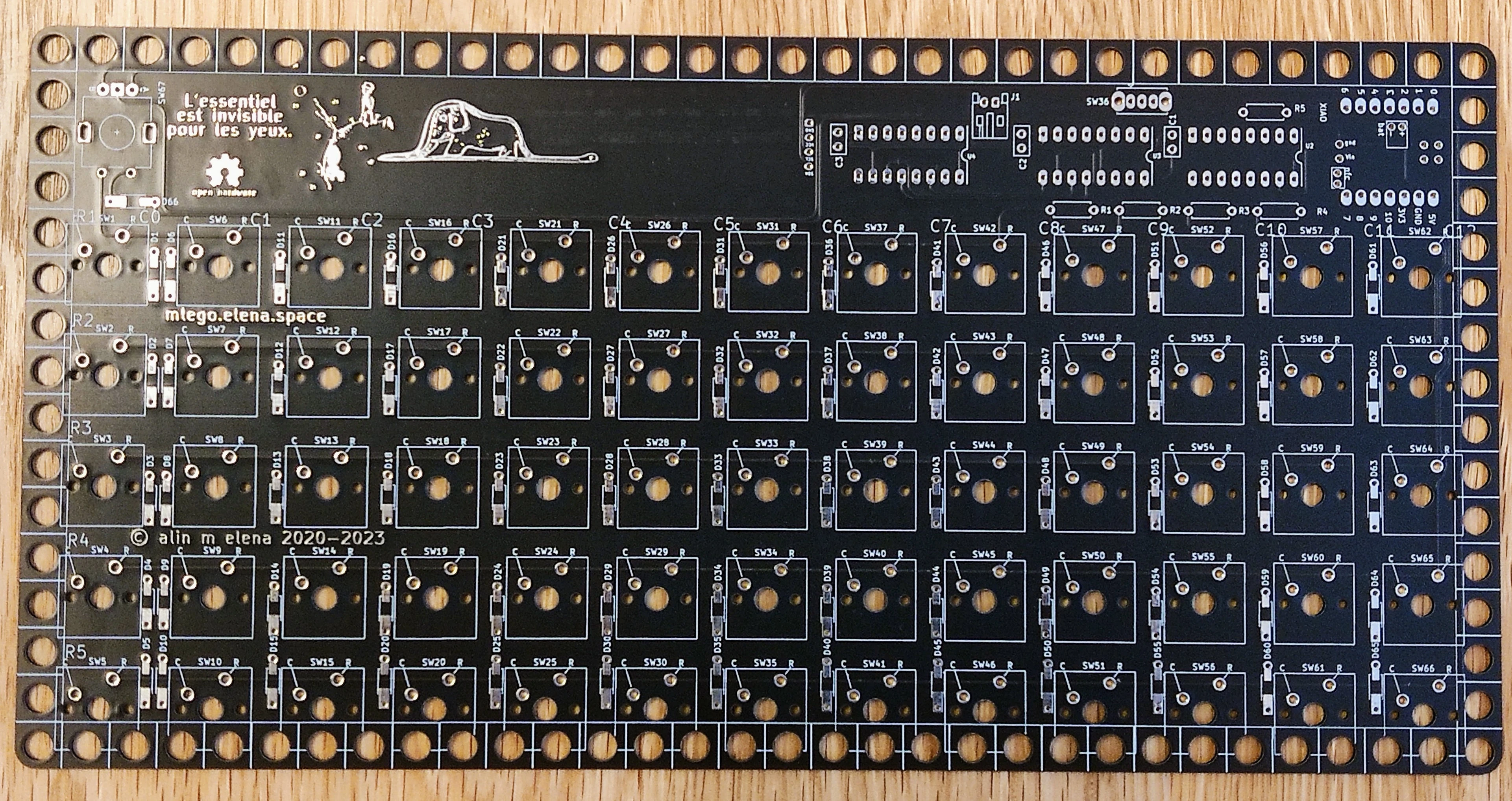
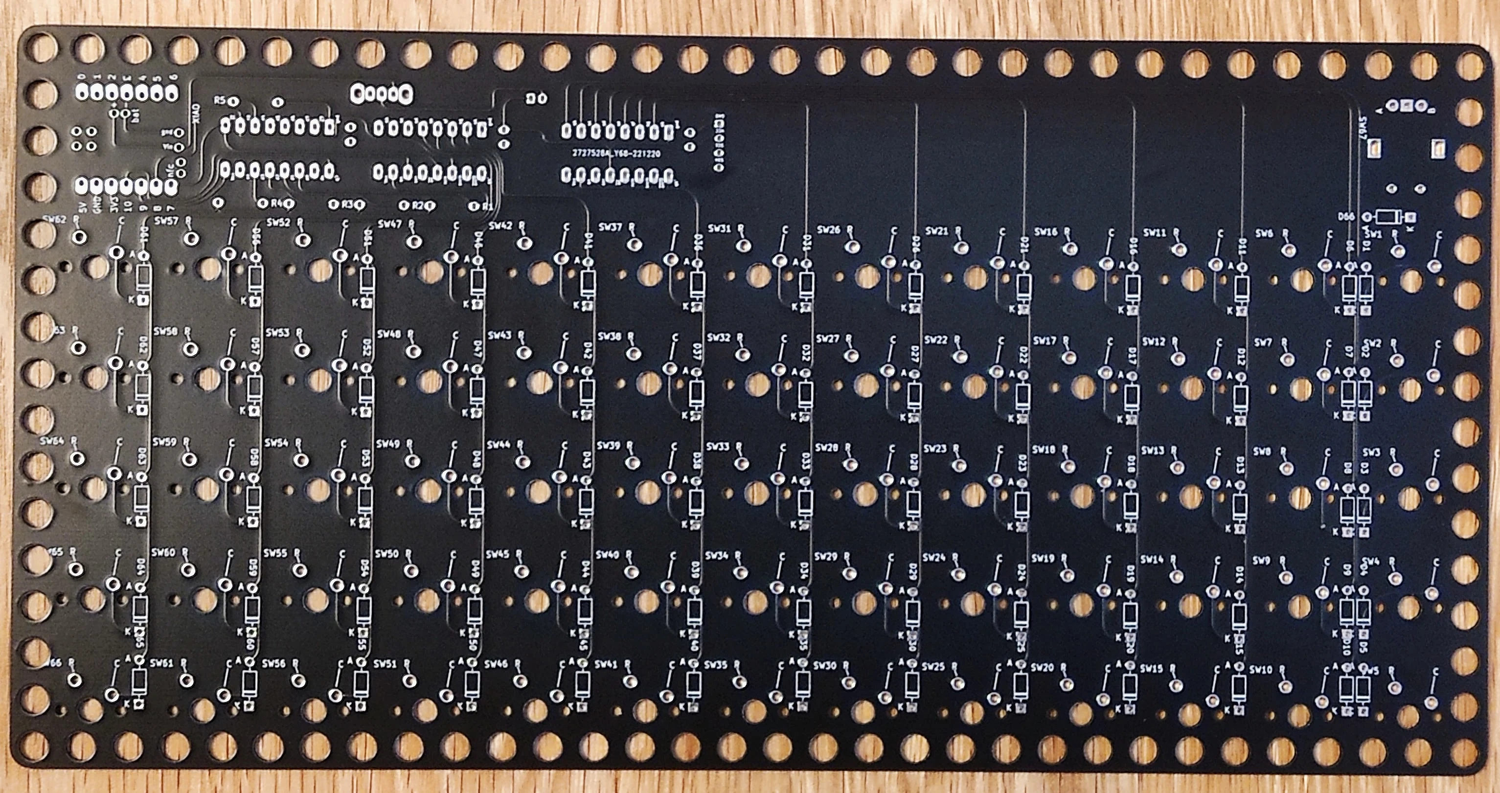
PCBs
Rev 4
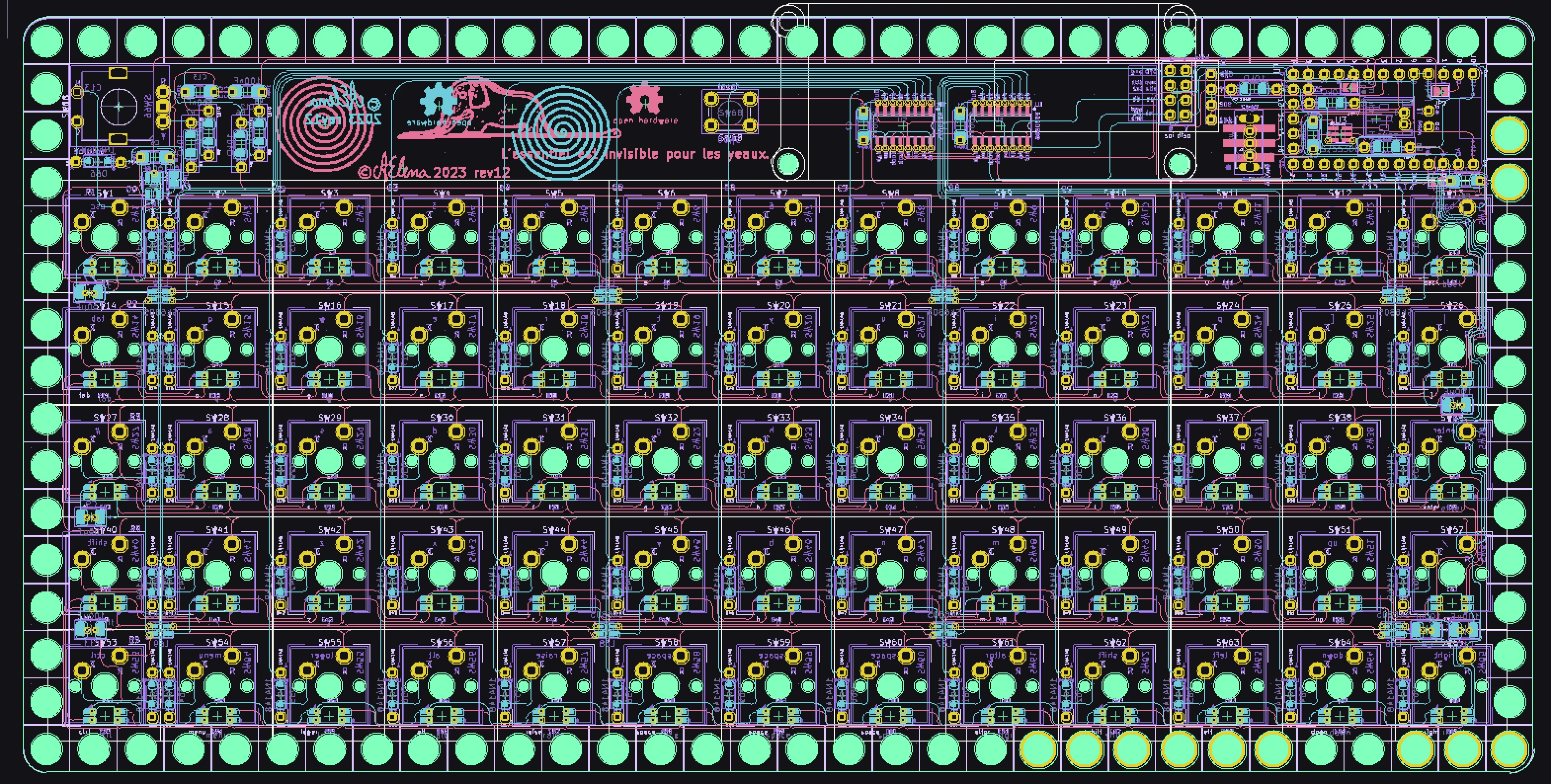
Rev 3
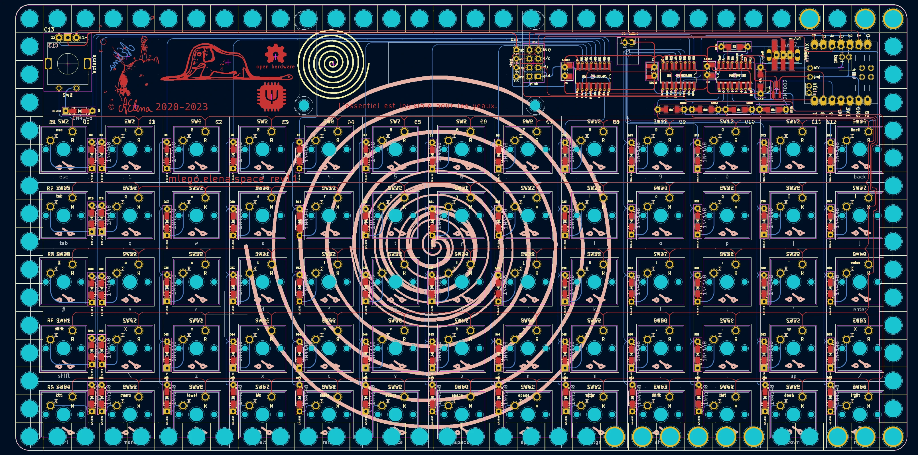
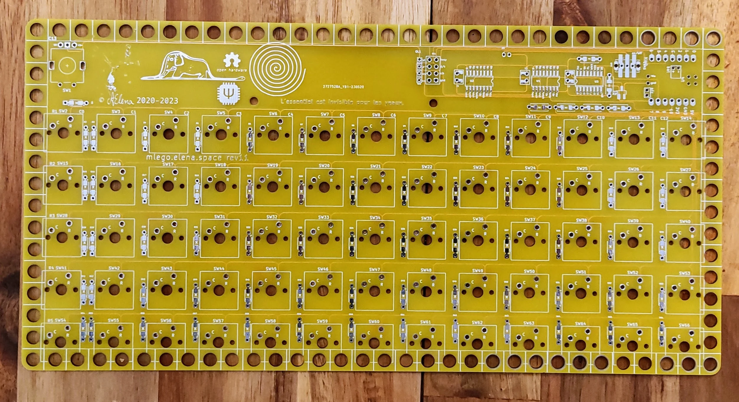
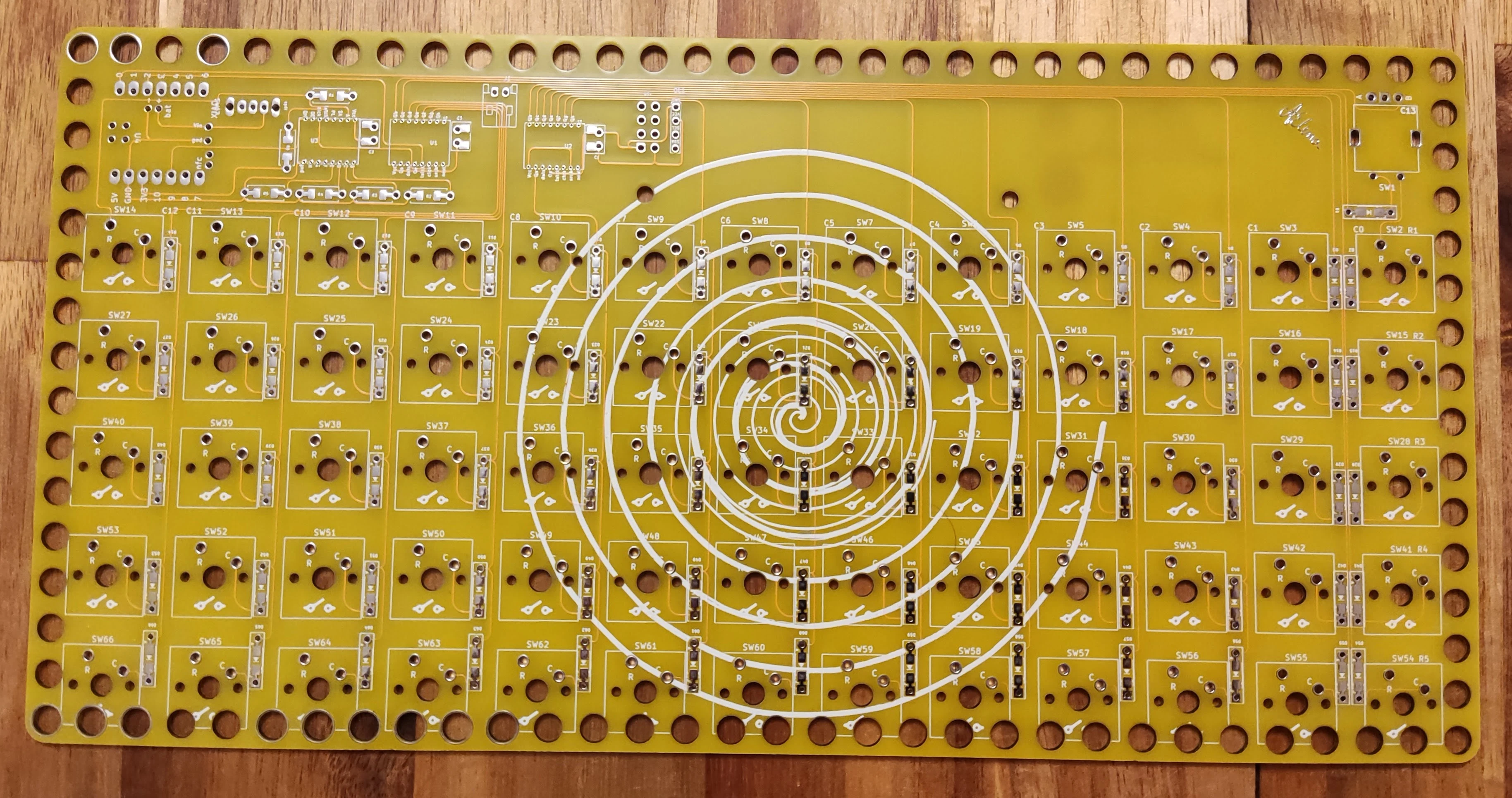
Rev 2
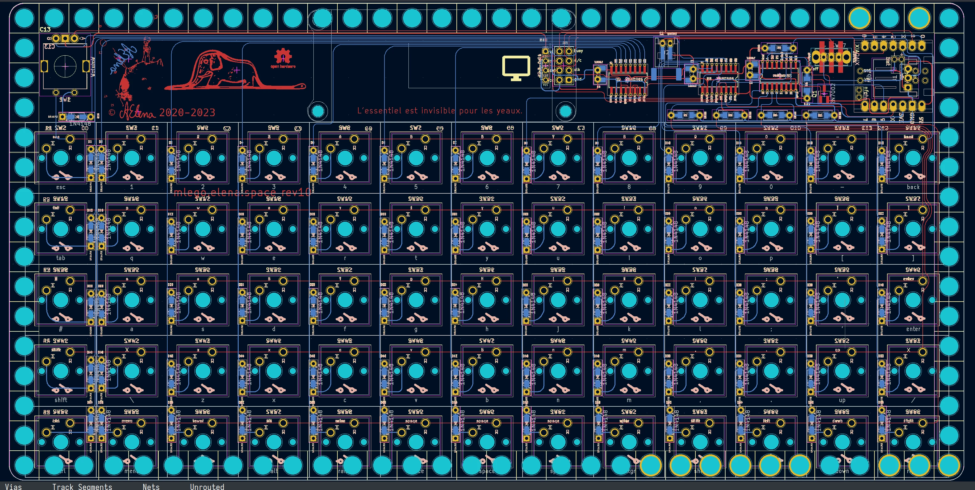
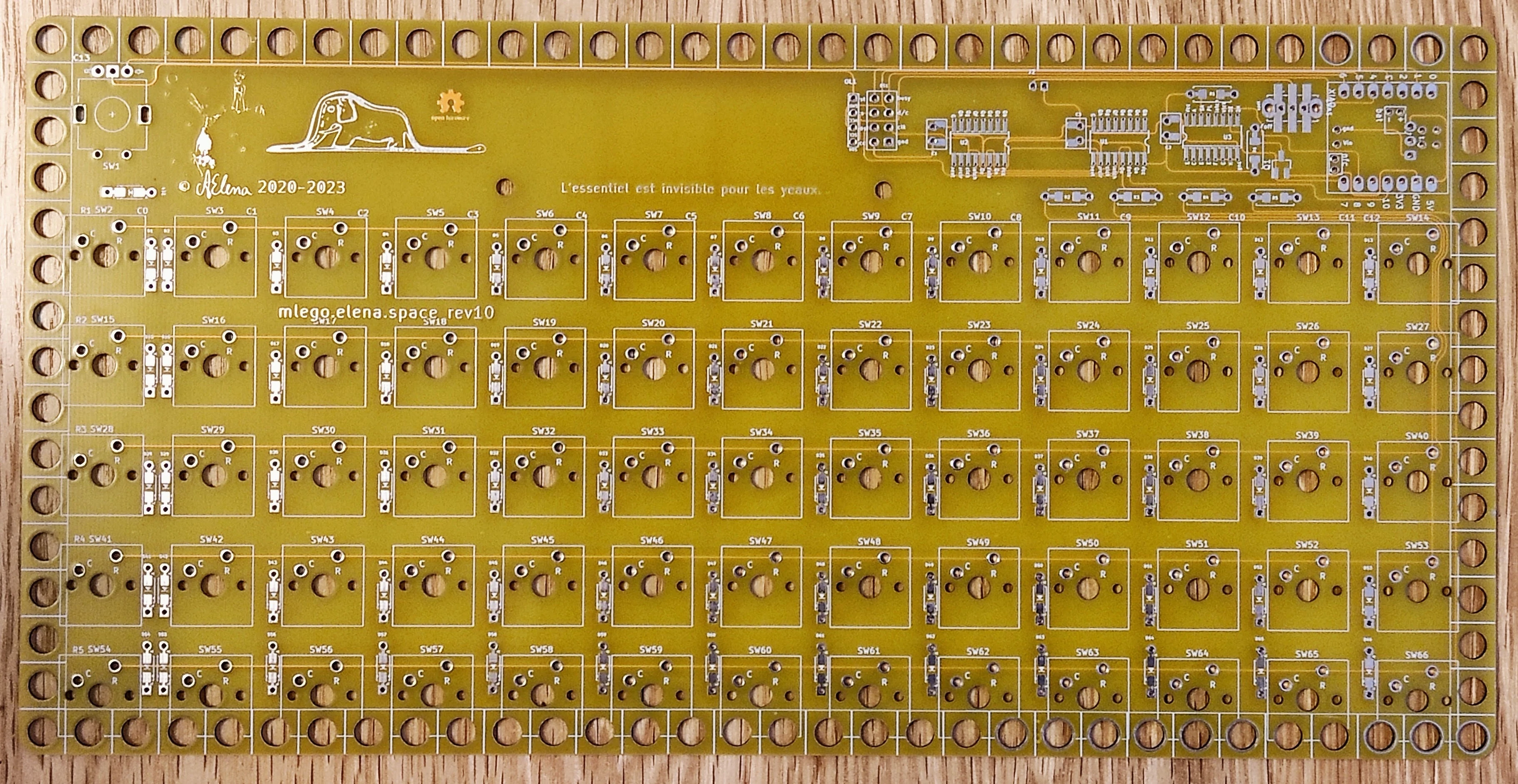
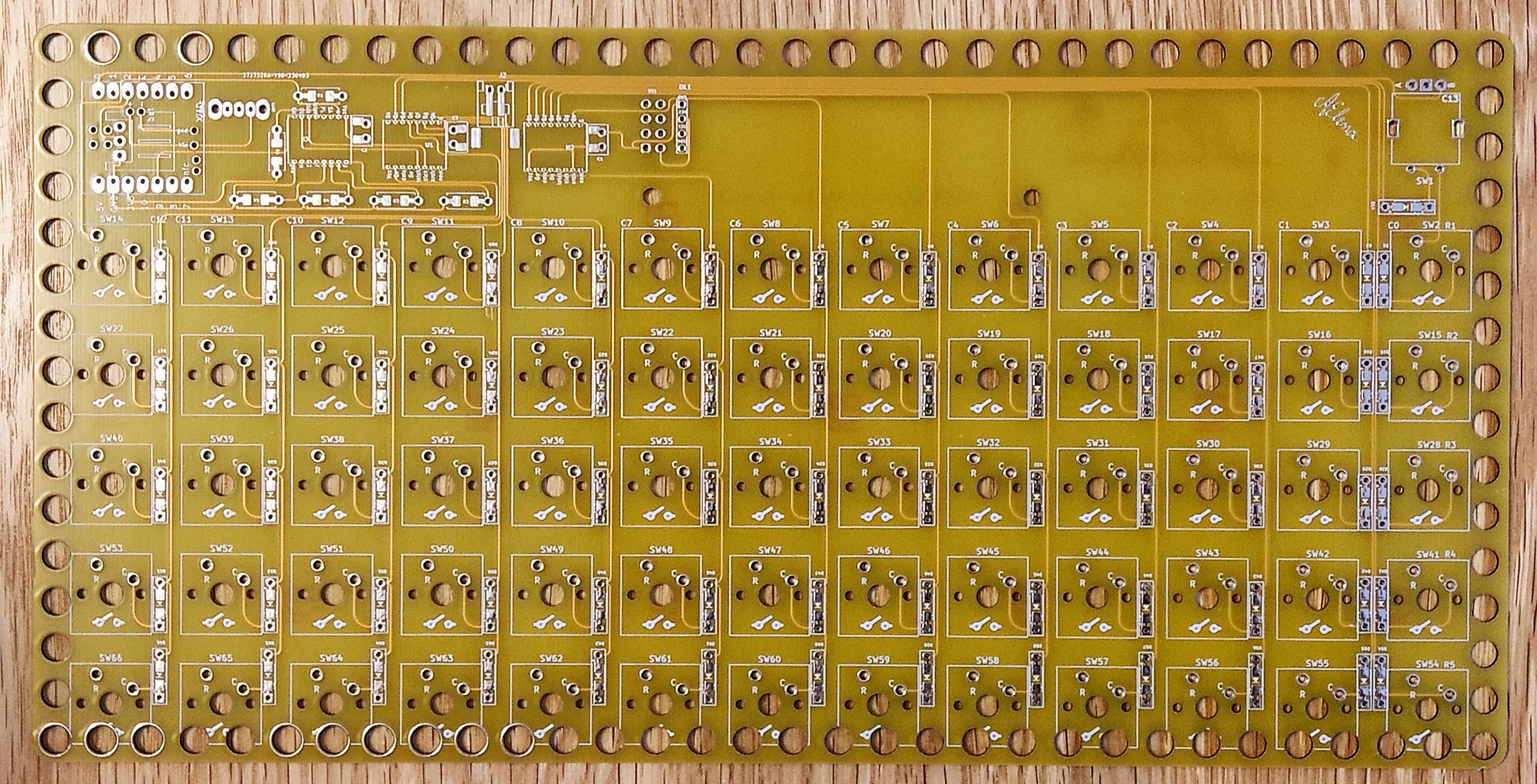
Rev 1
Gerbers & KiCad Source
Production-ready Gerbers for JLCPCB:
Full KiCad project files are hosted on GitLab (m-lego/m65). Note that the default branch HEAD is always work-in-progress; check out the specific revision tag/branch below:
KiCad Checkout
Rev 4
git clone https://gitlab.com/m-lego/m65.git
cd m65
git checkout m66-rev4
Rev 3
git clone https://gitlab.com/m-lego/m65.git
cd m65
git checkout revision11
Rev 2
git clone https://gitlab.com/m-lego/m65.git
cd m65
git checkout revision10
Rev 1
git clone https://gitlab.com/m-lego/m65.git
cd m65
git checkout revision9
Firmware
Both QMK and ZMK are supported. You can download prebuilt .uf2 binaries below or compile from source.
ZMK
Latest ZMK builds are available from the mlego-zmk GitHub Actions workflow (select the latest successful Build mlego run):
QMK Prebuilt UF2
- mlego_m66_rev4_default_rgb_screen.uf2
- mlego_m66_rev4_uk_rgb_screen.uf2
- mlego_m66_rev3_default.uf2
- mlego_m66_rev3_uk.uf2
- mlego_m66_rev2_default.uf2
- mlego_m66_rev2_uk.uf2
- mlego_m66_rev1_default.uf2
- mlego_m66_rev1_uk.uf2
Latest automated QMK builds can also be downloaded from GitHub Actions.
QMK Source Build
Rev 4
git clone --recurse-submodules -b mlego_dev https://github.com/alinelena/qmk_firmware.git qmk-alin
cd qmk-alin
qmk compile -kb mlego/m66/rev4 -km uk
qmk compile -kb mlego/m66/rev4 -km default
Rev 3
# OLED version
git clone --recurse-submodules -b mlego_dev https://github.com/alinelena/qmk_firmware.git qmk-alin
cd qmk-alin
qmk compile -kb mlego/m66/rev3 -km uk
qmk compile -kb mlego/m66/rev3 -km default

# E-Ink version
git clone --recurse-submodules -b mlego_eink https://github.com/alinelena/qmk_firmware.git qmk-alin
cd qmk-alin
qmk compile -kb mlego/m66/rev3 -km uk
qmk compile -kb mlego/m66/rev3 -km default
Rev 2
git clone --recurse-submodules -b mlego_dev https://github.com/alinelena/qmk_firmware.git qmk-alin
cd qmk-alin
qmk compile -kb mlego/m66/rev2 -km uk
qmk compile -kb mlego/m66/rev2 -km default
Rev 1
git clone --recurse-submodules -b mlego_dev https://github.com/alinelena/qmk_firmware.git qmk-alin
cd qmk-alin
qmk compile -kb mlego/m66/rev1 -km uk
qmk compile -kb mlego/m66/rev1 -km default
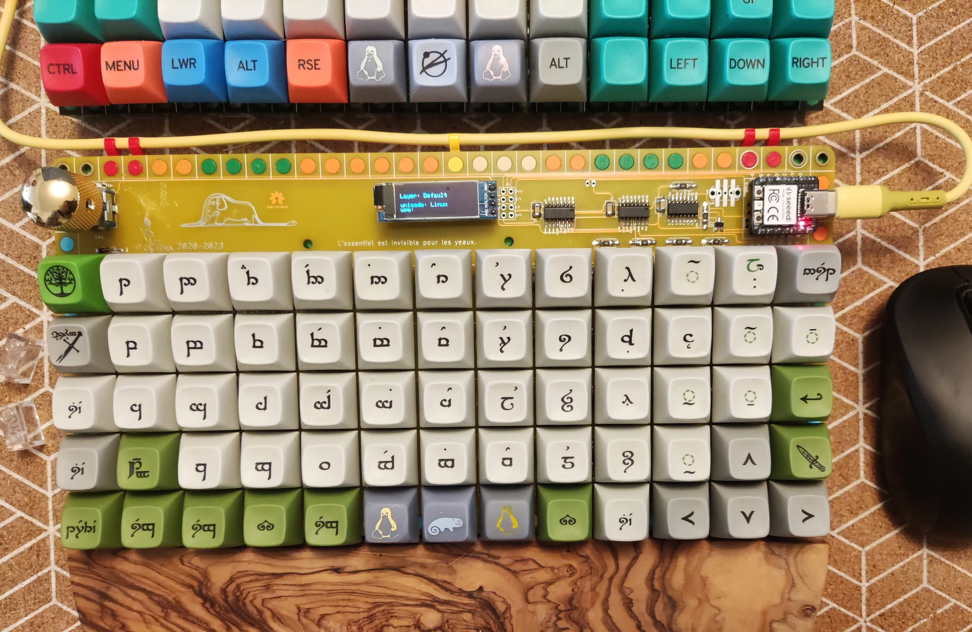
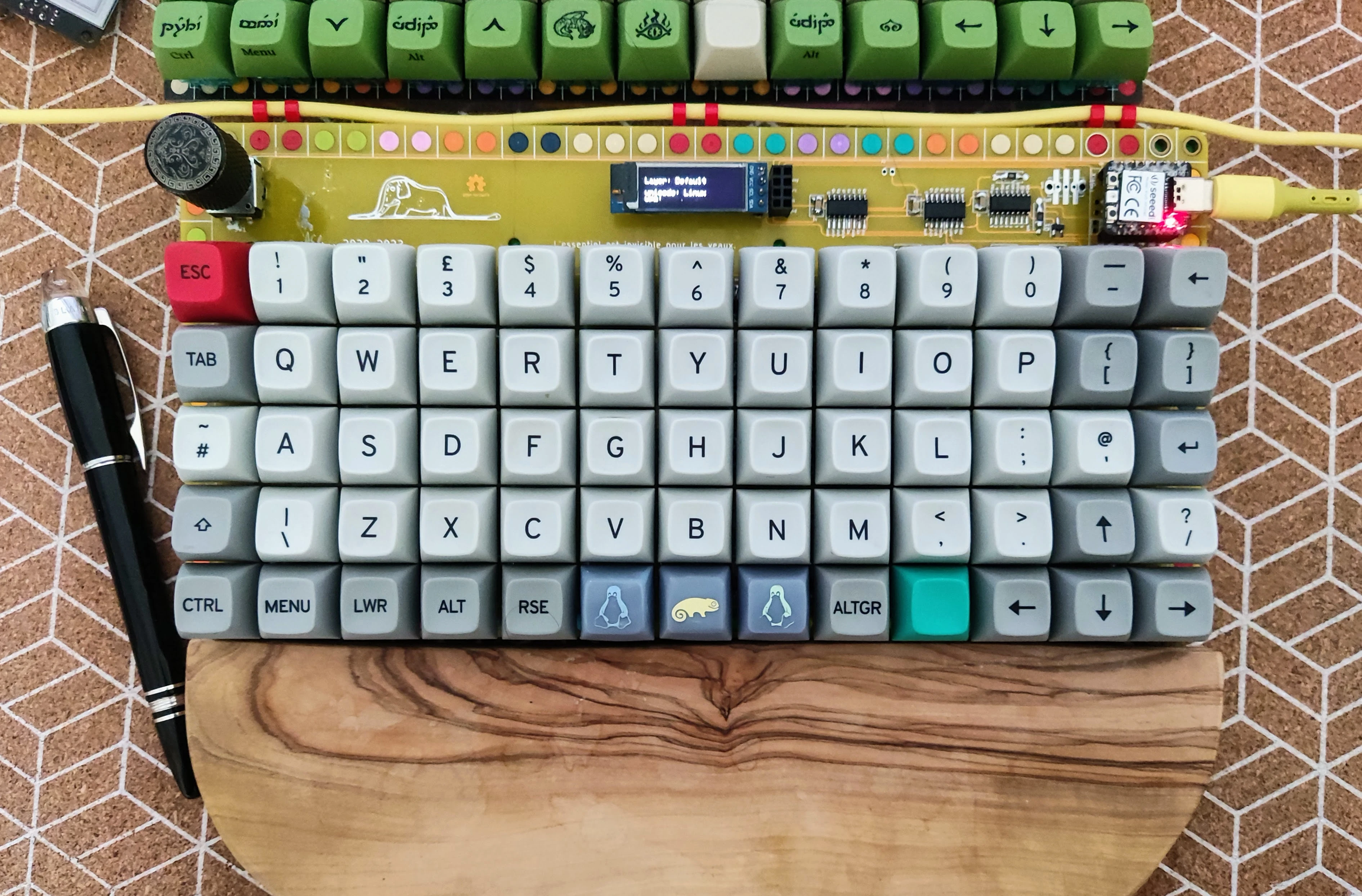
Build Gallery
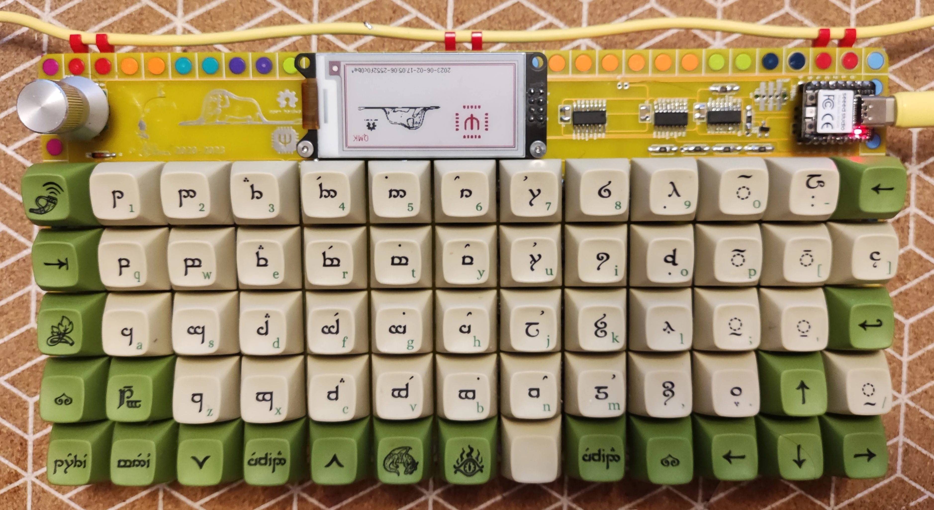
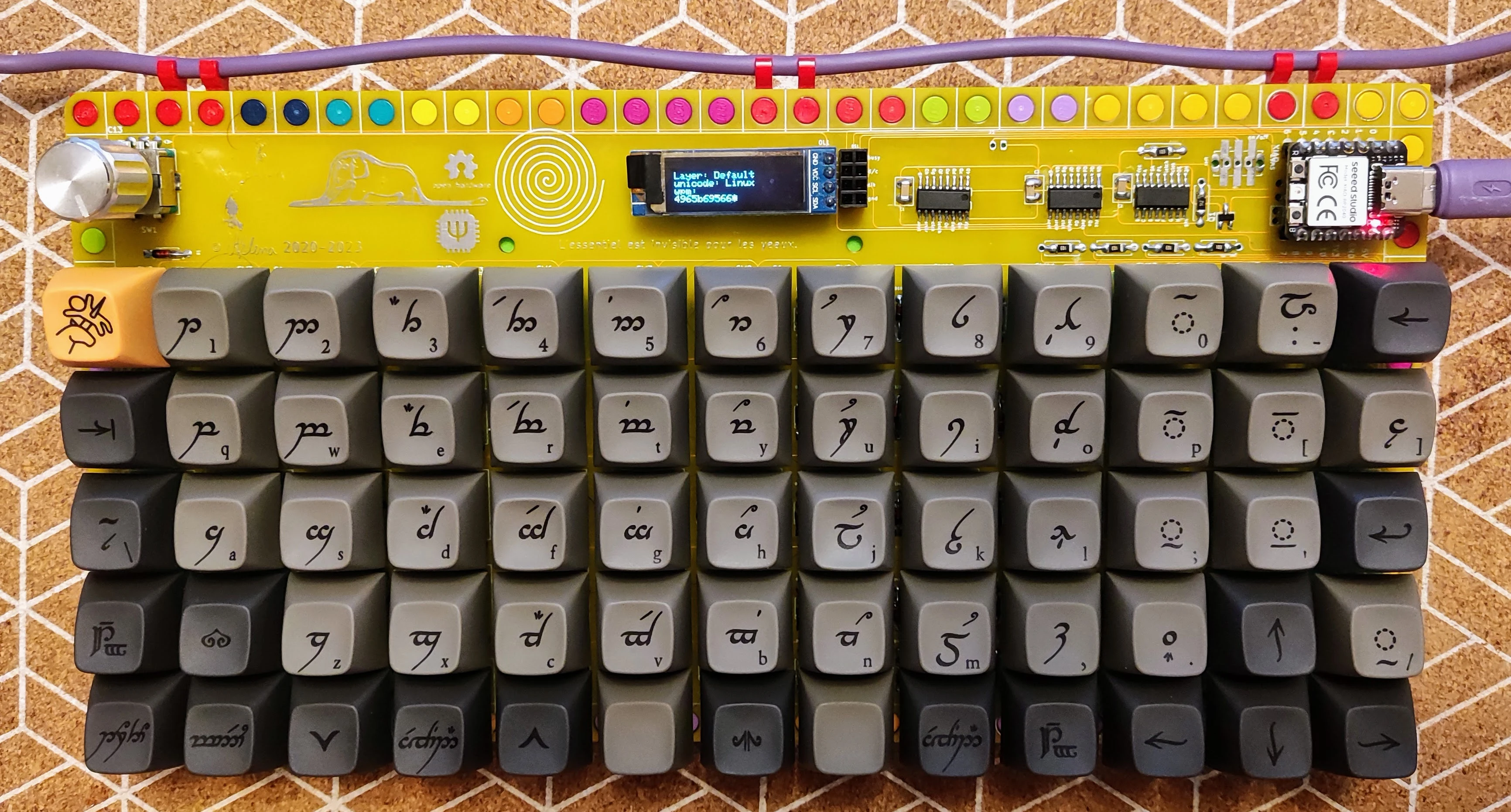
Rev 4
Rev 3
Rev 2
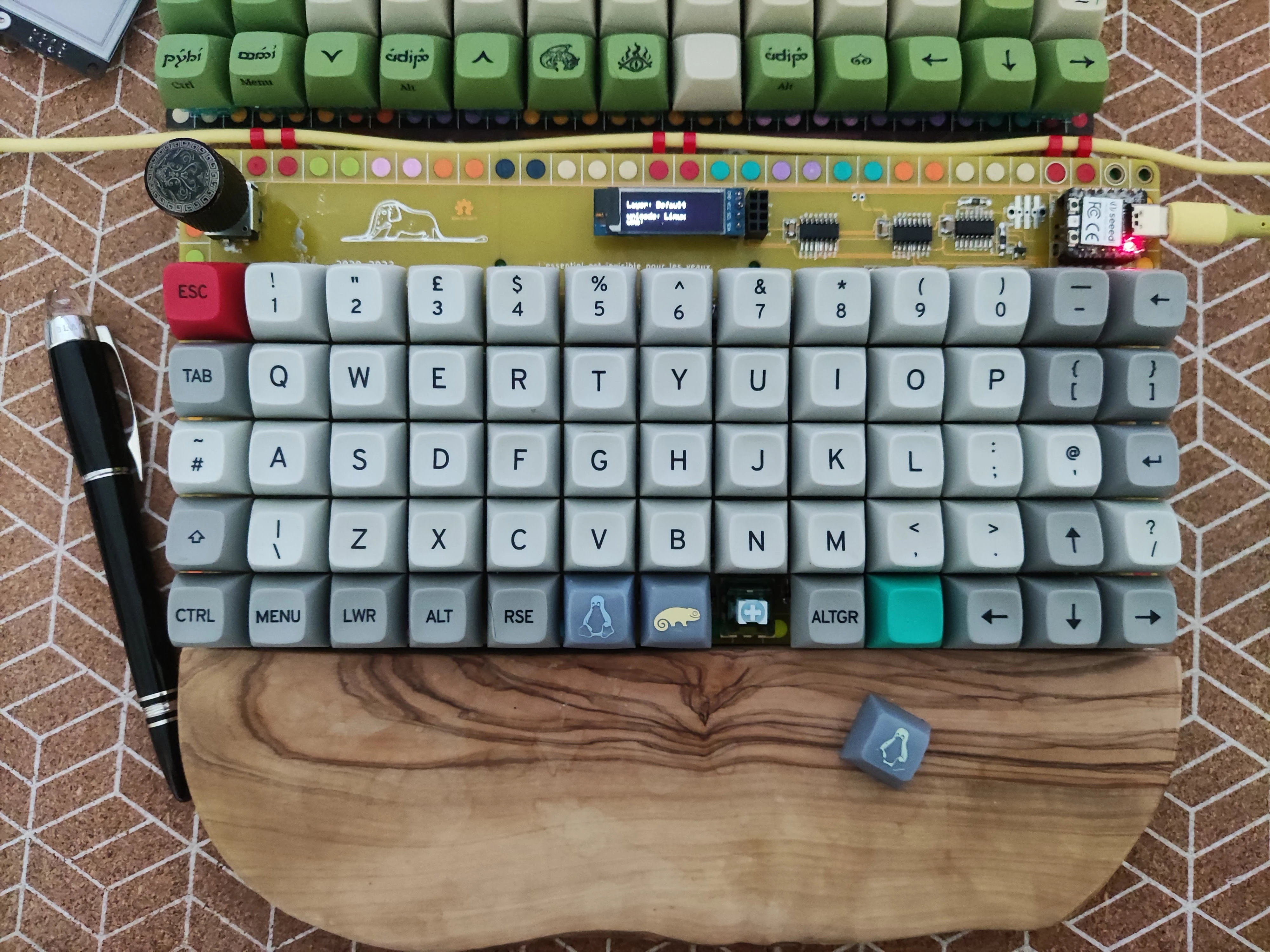
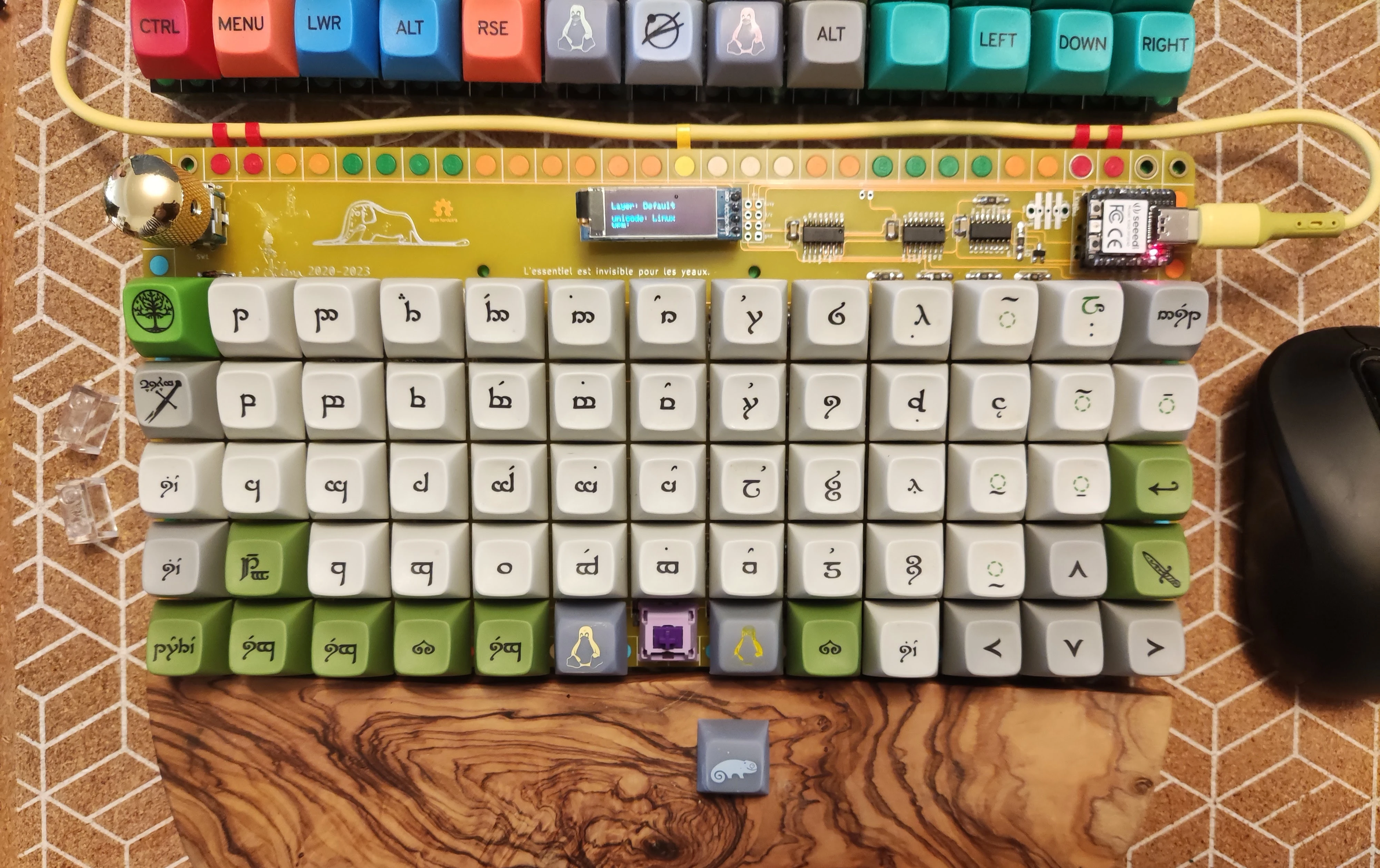
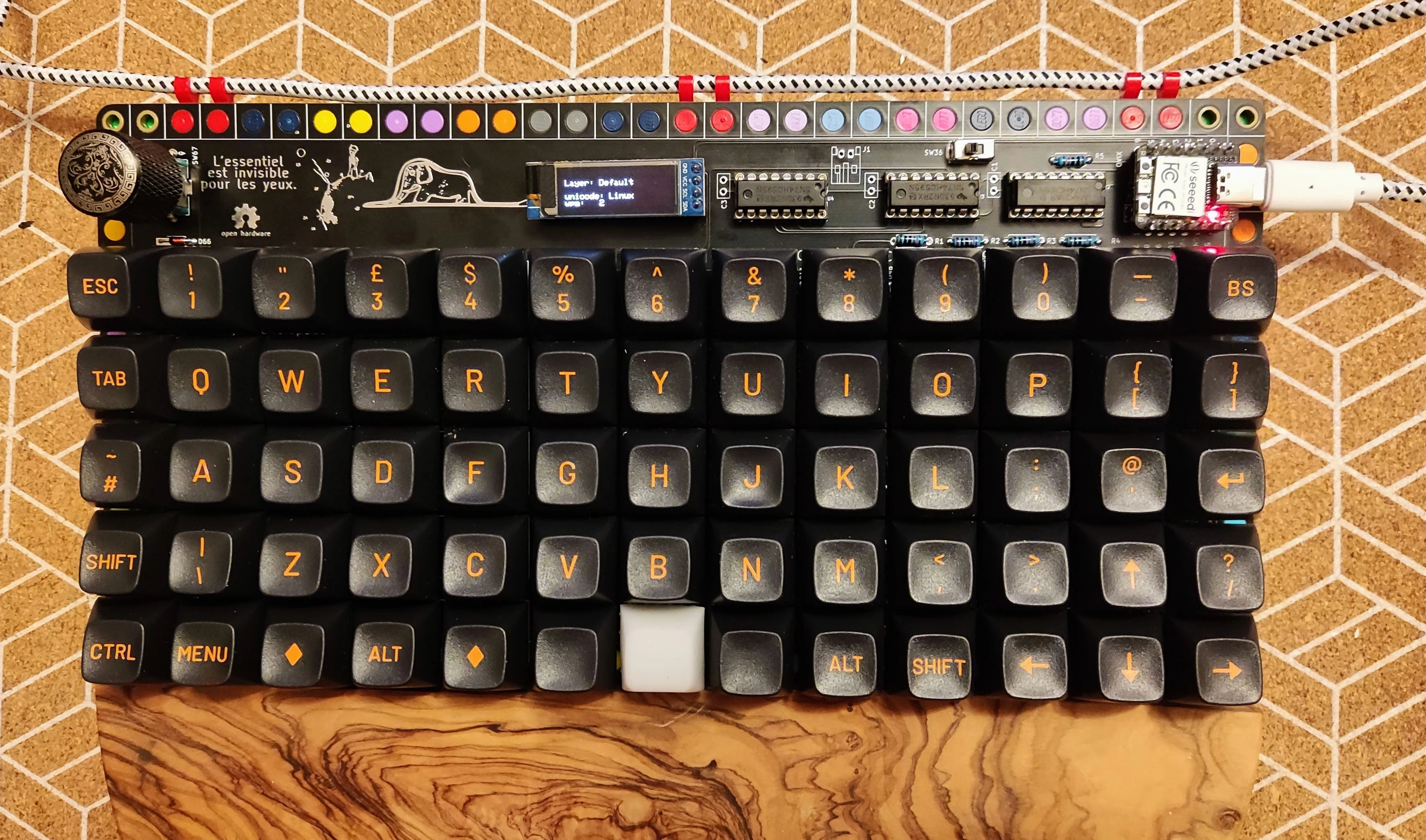
Rev 1
Keymaps & Layout
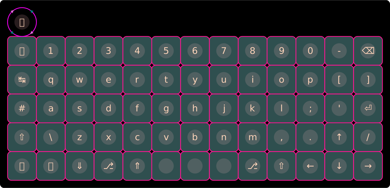
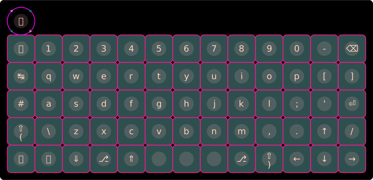
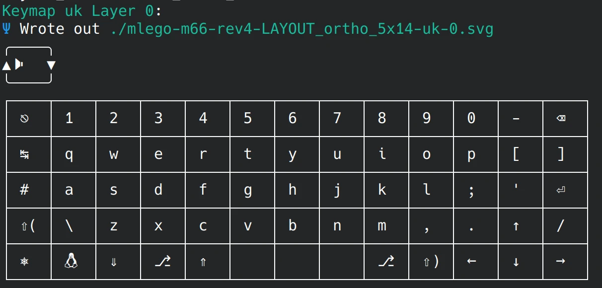
All m66 revisions share the same 5×14 physical layout and keymaps (shown below for Rev 4).
Physical Layout
Combined UK Keymap Summary
Except for mouse keys, QMK and ZMK keymaps are identical:
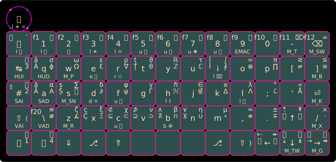
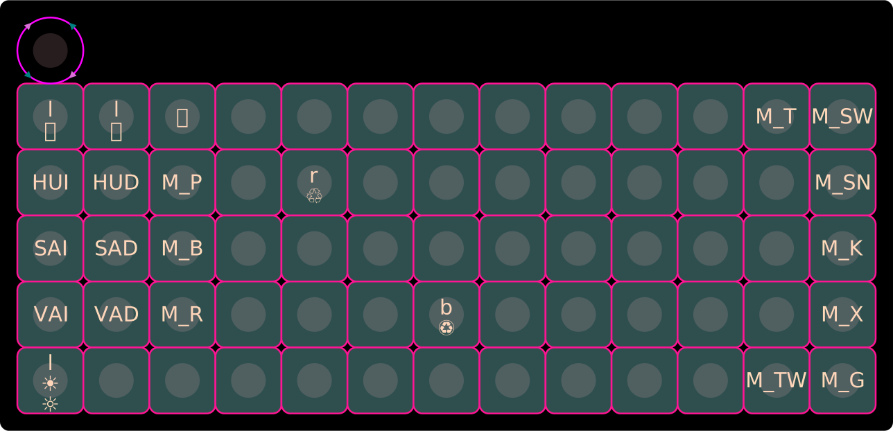
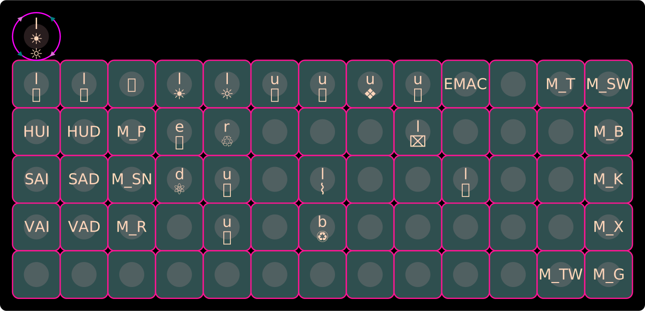
- Center legend: Layer 0 (Base) · Left legend: Layer 1 (Lower) · Right legend: Layer 2 (Raise) · Bottom legend: Layer 3 (Adjust)
- Legend codes:
lLighting ·uUnicode ·dDebug ·bBootloader ·eErase EEPROM ·rReset MCU
Default Keymap Layers
Layer 0 — QWERTY
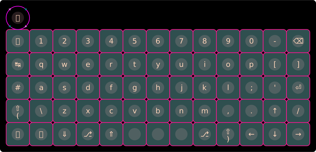
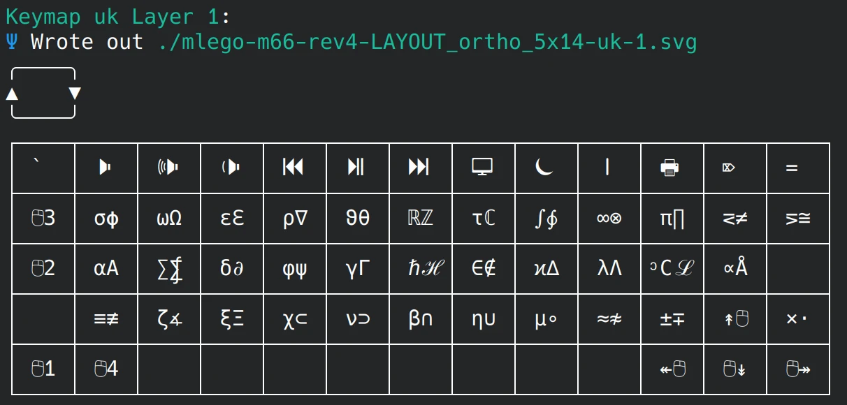
Layer 1 — Lower
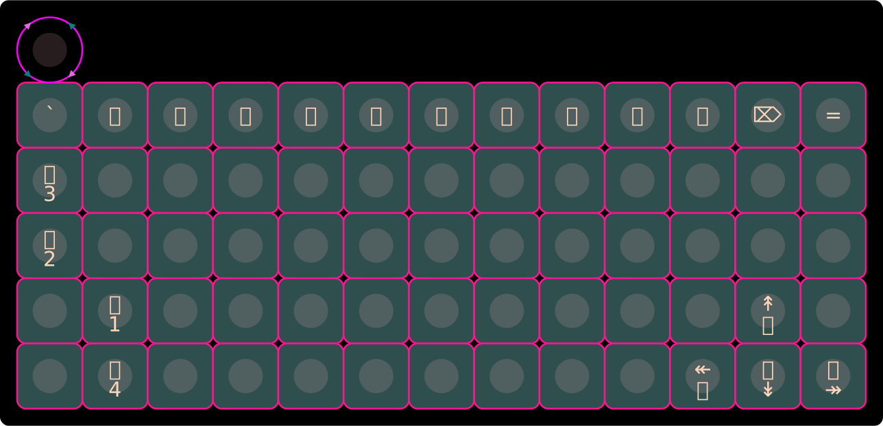
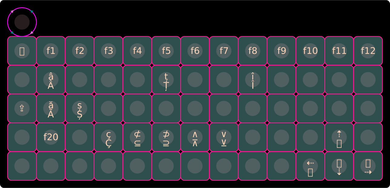
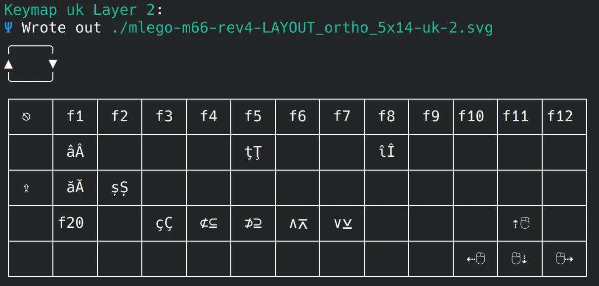
Layer 2 — Raise
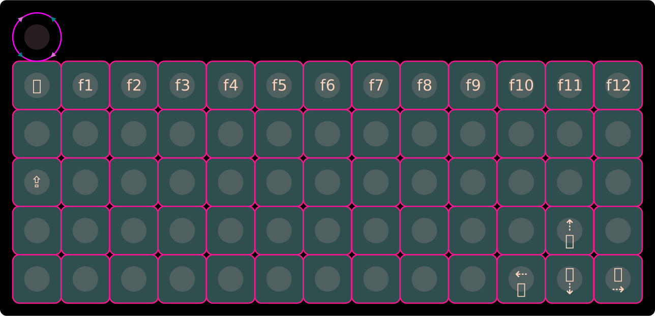
Layer 3 — Adjust
UK ISO Keymap Layers (with RGB Indicators)
Layer 0 — QWERTY
Layer 1 — Lower
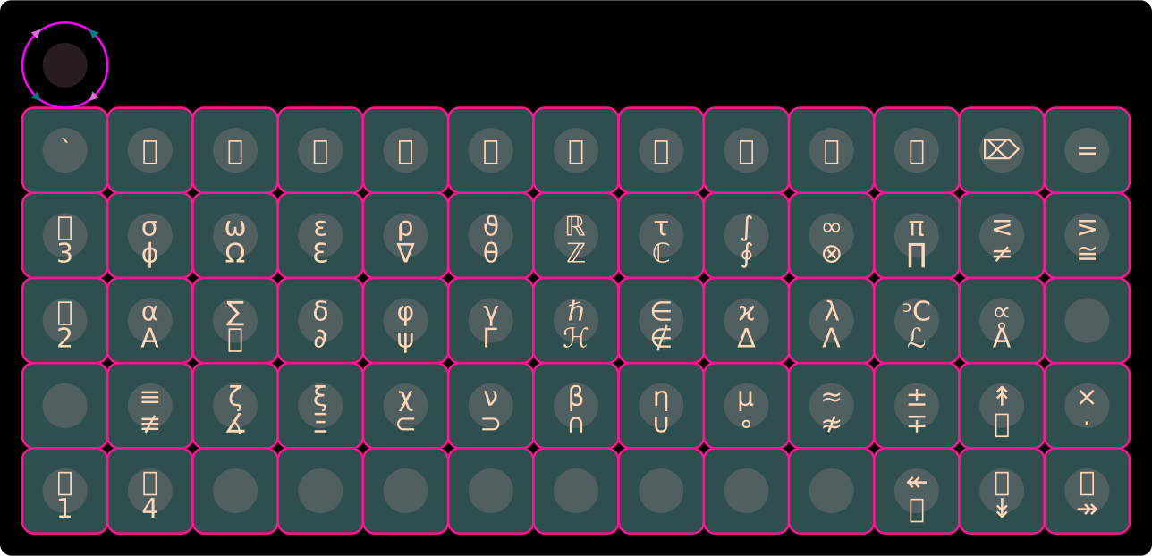
Layer 2 — Raise
Layer 3 — Adjust

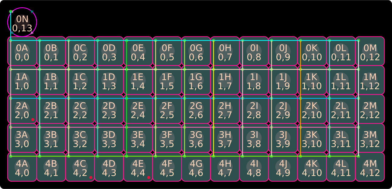
Matrix & Pinout Reference
Rev 4 (RP2040 Pro Micro)

Rev 3 (XIAO RP2040)

Rev 2 (XIAO RP2040)
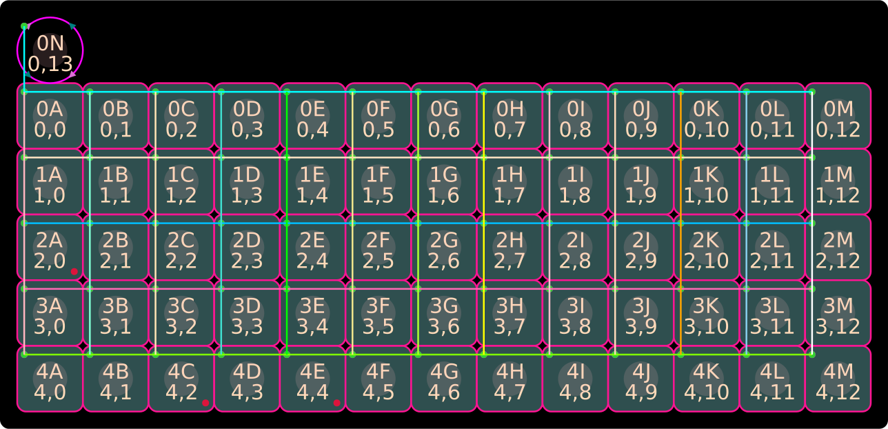
Rev 1 (XIAO RP2040)
ShiftRegister SN74HC595N (#1 & #2)        ShiftRegister 74HC165N (#3)
QB |1    16| VCC                          nPL |1    16| VCC
QC |2    15| QA                            CP |2    15| nCE
QD |3    14| SER data                      D4 |3    14| D3
QE |4    13| OE                            D5 |4    13| D2
QF |5    12| RCLK latch                    D6 |5    12| D1
QG |6    11| SRCLK clock                   D7 |6    11| D0
QH |7    10| SRCLR                        nQ7 |7    10| DS
 G |8     9| QH*                            G |8     9| Q7
| Rows | C0 | C1 | C2 | C3 | C4 | C5 | C6 | C7 | C8 | C9 | C10 | C11 | C12 | C13 | Row Pin |
|---|---|---|---|---|---|---|---|---|---|---|---|---|---|---|---|
| R0 | Esc | 1 | 2 | 3 | 4 | 5 | 6 | 7 | 8 | 9 | 0 | - | Bksp | MUTE | 3D0 |
| R1 | Tab | q | w | e | r | t | y | u | i | o | p | [ | ] | X* | 3D1 |
| R2 | # | a | s | d | f | g | h | j | k | l | ; | ' | Enter | X* | 3D2 |
| R3 | Shift | \ | z | x | c | v | b | n | m | , | . | Up | / | X* | 3D3 |
| R4 | Ctrl | Menu | Lower | Alt | Raise | Space | Space | Space | AltGr | Shift | Left | Down | Right | X* | 3D4 |
| Col Pin | 2QB |
2QC |
2QD |
2QE |
2QF |
2QG |
2QH |
2QA |
1QH |
1QG |
1QF |
1QE |
1QA |
1QD |
(X NC)* |
- Encoders:
Pad_A = GP27,Pad_B = GP26 - OLED (I²C):
SCL = GP7,SDA = GP6 74HC595N(Columns):MOSI = GP3(pin 11),Latch = GP1(pin 8),Clock = GP2(pin 9)74HC165N(Rows):Latch = GP1(pin 8),Clock = GP2(pin 9),MISO = GP4(pin 10)- LEDs (RP2040):
CAPS_LOCK = GP25,Lower = GP16,Raise = GP17,RGB DI = GP12,RGB On = GP11